Introduction: Atari Punk Console Synthesizer
The Atari Punk Console is an easy to build synthesizer that uses two 555 chips to give a range of different sounds. It got its name from the DIY
electronic music world because it sounds vaguely like the tones the
classic Atari made. However, it is known in more boring electronics
circles as a Stepped Tone Generator. It is basically an astable
multivibrator circuit triggering a monostable multivibrator circuit. If
that sounds terrifying to you, fret not. You will see how simple this is
once I explain.
To learn more about the integrated circuits such as the 555 chip used in this project, check out the Electronics Class.
Step 1: Materials
For this project you will need:
(x2) 555 chips
(x1) 1K resistor
(x2) 4.7K resistors
(x1) 0.1uF capacitor
(x1) 0.01uF capacitor
(x1) 10uF capacitor
(x1) 500K potentiometer
(x1) 500K potentiometer with built-in switch
(x1) Tactile transducer (or speaker)
(x1) 9V battery snap
(x1) 9V battery
(x1) Hammond BB-sized enclosure
(x2) Knobs
(x2) 6-32 x 3/4" bolts
(x2) 6-32 x 1/4" nylon spacers
(x1) Adhesive-backed velcro
(x4) Adhesive rubber feet
(x1) Matte white sticker paper (for printer)
Step 2: Monostable Multivibrator
There are many ways a 555 can be configured, but the most basic is in monostable multivibrator mode. When configured in monostable mode, the 555 timer is triggered by a low (or ground) pulse on pin 2 (the input pin). In other words, it is triggered when pin 2 is connected to ground.
After being triggered, the 555 chip then produces a high (or power) pulse on pin 3 (the output pin). The length of this pulse is determined by the resistor and capacitor connected to pins 6 and 7. This particular combination of resistor and capacitor is called an RC timing circuit. Basically, an RC timing circuit works by limiting the rate at which the capacitor charges by placing a resistor in series with it from power. By changing the values of these two components, you can adjust the length of the pulse produced. For instance, notice what happens when the potentiometer in the example is tweaked.
To more fully explain, when the 555 is triggered on Pin 2, the internal circuitry changes and allows pin 7 to begin charging the external capacitor. This charging process triggers a high pulse on the output pin (pin 3). The capacitor then starts to recharge through the external resistor. However, the resistor limits the speed with which the capacitor can recharge, and this determines the length of the pulse.
When the capacitor gains enough voltage, it tells pin 6 it is high again (or powered). This causes pin 7 to be toggled back into its original state, which discharges the capacitor once more. When the capacitor discharges, the pulse on the output pin goes low once again. At this point, the circuit goes back to being dormant and waiting for another input.
In short, every input produces a single pulse on the output.
Step 3: Astable Multivibrator
The 555 can also be configured as an astable multivibrator. When configured in astable mode, the 555 timer runs as an oscillator. In simple terms, an oscillator is a circuit which oscillates an electrical signal between high (on) and low (off) at a steady rate. This produces a square wave on the output. Unlike the monostable mode which produces a single pulse once when triggered, this circuit produces the same pulse over and over without any external input.
By connecting together pins 2 and 6, a feedback loop is created where the chip is able to re-trigger itself after every pulse.
It works very similarly to the monostable version, but with some key differences. The capacitor slowly charges based on the values determined by the potentiometer and resistor, which are in series. In this way, it is basically just a timing circuit with two resistors in series to power, instead of just one. However, the 100K resistor is straddling pins 6 and 7. This allows the capacitor to discharge through the resistor to pin 7. Rather than coming to a state of rest like in monostable mode, pin 6 then pulls pin 2 low again, restarting the cycle.
In short, this circuit produces a square wave that is adjusted by the potentiometer.
Step 4: Combine the Two
By now you are probably wondering what the heck I am talking about or why.
When you replace the switch of the monostable circuit with output waveform coming from pin 3 the astable circuit, something interesting happens. Every time the astable oscillator goes to ground, the monostable oscillator is triggered and produces a pulse determined by its RC timing circuit.
By adjusting the two potentiometers in the different circuits, you can adjust both the frequency of the astable oscillator square wave and the pulse width of the monostable oscillator.
If we were to think of this as a musical device, it is basically like adjusting the octave, and the notes of the musical scale. I bring this up because if you were to make the output of this circuit fast enough, and send it through a speaker, it would displace air at different frequencies that we can hear.
Step 5: Making Audio
Humans can hear frequencies over 20 hertz as a tone. That is much faster than the circuit is currently going. Thus, if we want to connect our output from our 555 circuit to a speaker to hear a tone, we will need to speed it up a bit. This requires changing some of the values of the different components to make the waveform faster.
To begin, we need to drop the value of the resistor to 1K ohm to allow for faster triggering of the astable oscillator. We are also going to change the values of the capacitors to be 0.01uF for the astable multivibrator and 0.1uF for the monostable multivibrator. Both potentiometers should be 500K ohm in order to be able to sweep through the range of audible frequencies.
Another tweak we are going to make is to add 4.7K resistors in series with both of the potentiometers. The reason for this is that as the resistance gets down to zero, the pin gets pulled high, and the audio cuts out. To ensure there is always a little bit of resistance between the pin and power supply, we will just add a resistor in series with the potentiometer so the resistance can never drop below the value of the resistor.
Finally, we will add a 10uF capacitor on the output to the speaker. This is a filter which removes unwanted noise from the circuit.
Step 6: Enclosure
Once again, after breadboarding the circuit, the first thing we are going to do is prepare the enclosure. This is an easy one since we largely just need to mount two potentiometers and a circuit board.


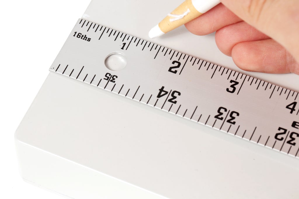
We will start by measuring and marking 1-1/4" in from the shortest edge, and then 1-1/4" in from the longest edge on the face of the enclosure.

Next, we will make a drill guide by tapping the center of these markings using a nail.


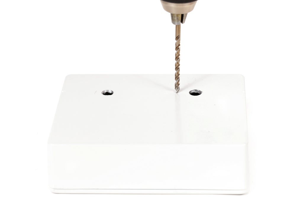
Drill pilot holes using an 1/8" drill bit.


Then, drill the pilot holes to the proper diameter for the potentiometers. In my case this was 9/32" and 5/16". The potentiometer with the switch had a slightly larger diameter shaft.

Finally, insert the potentiometers in backwards and upsides down, and wiggle them back and forth to make a small marking for their mounting tabs.

Drill holes for the mounting tabs using 1/8" drill bits.
Step 7: Circuit Board Mounting Holes
Next, flip the board over and place the circuit board on one of the inside corners of the lid.
Mark the board's mounting holes onto the inside of the box lid.
Drill through these markings with a 1/8" drill bit to make mounting holes.
Step 8: Build the Circuit
Hopefully you have already built and tested the circuit on a breadboard. If not, I highly recommend doing that first.
If that is good and done, build the circuit board as outlined in the schematic above. You can double check your work both against the schematic and your connections on the breadboard.
Keep in mind these images shouldn't be used as a guide for building the circuit. These are largely just meant to show you my process for assembling the circuit board and not as the definitive guide for constructing these boards. Always go by the schematics!

Anyhow, I first attached the chips to the center of the board. This provides a point of reference for all of the other connections.

Next, I attached the resistors.

I then followed up the resistors with all of the capacitors. By now, all of the components should be attached.

The power connections were made next. I counted the number of pins connected directly to power to make sure this was correct.

I then followed an identical process for connecting the ground wires.

Finally, I made all of the other wire connections that were not connected directly to either power or ground, save for the components external to the board.
Step 9: Wire the Potentiometers
With both potentiometers facing you, wire a red wire to the right pin, and a green wire to the middle pin.
Also, connect two red wires to the switch terminals on the bottom of the potentiometer with the power switch.
Step 10: Connect the Potentiometers.
Connect the potentiometers and the power wires to the board as specified in the schematic.
Step 11: Speaker
Connect the red wire from the speaker to the negative side of the potentiometer and the speaker's black wire to ground.

In this project I am using a special type of speaker called a tactile transducer. This is basically a 'contact speaker'. What I mean by this is that instead of vibrating a cone and moving air, it is built in such a way that it vibrates whatever surface it is attached to, and that surface is vibrated to displace air and make sound. This is cool because nearly any solid surface can be vibrated to make sound.
Step 12: Install the Potentiometers
Install the potentiometers in the enclosure using their mounting hardware.
Step 13: Velcro
Attach the 9V battery to the inside of the enclosure using adhesive-backed Velcro tabs.
Step 14: Attach the Tactile Transducer
Using a strong double-sided tape such as carpet tape, affix the tactile transducer to the inside of the enclosure's lid.
Anywhere you affix it on the enclosure should make noise about equally well.
Step 15: Knobs
Turn each potentiometer fully to the left, and then press the knobs onto the shaft such that they are pointing at 7 o'clock.
Step 16: Finishing Touches
Decorate the enclosure as you see fit.
To stick with the Atari theme, I added this Atari-inspired rainbow swoop.
Step 17: Rock Out
When you are ready to begin your career as an experimental techno musician, turn it on and drop the beats.


