

Introduction: Audio Spectrum Visualizer IN-13, 7 Band.


Hello Guys,
This project was a long journey. I developed, tested and choose each part carefully. One step at the time, the whole project have forward slowly. But at the end. Wow it's an amazing product. Very proud of it. Lets begin.
Supplies

Part is available here Version 1.2
Almost all parts came from digikey.
In the part list you will find all part number needed.
Few other part came from ebay like IN-13 or tube acrylic holder.
This is not a cheap project. There are many parts and some are expensive. IN-13 are not in production anymore.
You will need to put some money and time in it. All is hand crafted except for pcbs. Tube are fragile and take a lot of care. At the end the result is unique and very beautiful.
Step 1: Specifications

Specifications I wanted:
- 7 Bands IN-13 tube.
- Hardware FFT
- RCA input
- Microphone input
- Low floor noise
- Auto On
- Auto Off
- Volume control as well
- Real Frequency Respond
- No negative power supply
- Integrated frequency generator to adjust each tube
- Invert mode. To put 2 spectrum side by side one mirror of the other.
- One PCB for everything, HVPS include.
- No add-on china module
Step 2: HVPS
Nixie in-13 are working at around 140 vdc. We will use a power adapter of 12v.
Let's making a HVPS for this.
The idea here is to short to GND a coil at high speed. This cause back EMF spikes of many many volts.
We add a diode to grab this spike and we accumule those spike in a capacitor.
A feedback (output voltage sample) is returning back to the controller and this one adjust the duty cycle (duration time) of the PWM (the coil shorted to GND). More the coil is shorted more the spike will be huge. But if the time is too long, the coil will just burn.
This idea is called a boost converter and many chip controller are available to do this.
On my nixie clock, i didn't have a controller. In fact, the uC was doing the PWM. The load is not moving so the PWM do not need to be change or adjust.
But with a graphic band visualizer, the load is constantly moving. In that case, we will use a step up (boost) controller.
Many could do the work.
UC3843B, available from texas instrument, ON semiconductor, STMicroelectronics. This is an old chip cheap and always in production. Texas datasheet, ON datasheet, ST datasheet $0.58 usd
MAX1771, only available from Maxim Integrated. datasheet. Nick de Smith have already done a psu for this purpose here. Results are very good. $5.00 usd. See more details later why we can't use it.
Step 3: The Coil... Optional Basic Experience, Attention, High Voltage!

First, the choice of the coil. Must be around 2A with low resistance DC.
SDR1307-101KL is looking good. 1.9A, 0.180 ohm, 13 mm round, surface mount, good price.
B82479A1 also have nice specification for our needs.
I draw and try this schematic. This is just a test on prototype board. We can't have good efficiency this way. This is to demonstrate the principle of operation.
Frequency input will be TTL 5v from 20kHz to 70kHz 50% duty cycle
Step 4: Trying HVPS


I did 5 HVPS with different controllers, different pcb arrangement. The goal here was to find a good efficiency, low cost part with low noise.
I also tried Nick HVPS here
The author here did a very good job. And yes the efficiency is 85% I tested it. The max 1771 give a modulated frequency to drive the mosfet. The modulated frequency is lower than 20khz and this bring me a big problem. I was seeing it on the tube! Definitely not a good thing. I had no choice to draw something myself for my needs.
Finally I choosed the UC3843B and clock it to 36kHz. At this speed, this isn't transmitted on the tube, problem solved. I did 4 littles pcb to tried different configuration of component until, under test, was perfect.
1 tube take 71ma. 7 tubes full turn on takes 500ma for a total of 6w only. My power supply can go to 10 watts easily.
Step 5: Final HV Power Supply Schematic

Step 6: Audio Spectrum Visualizer IN-13 Schematic
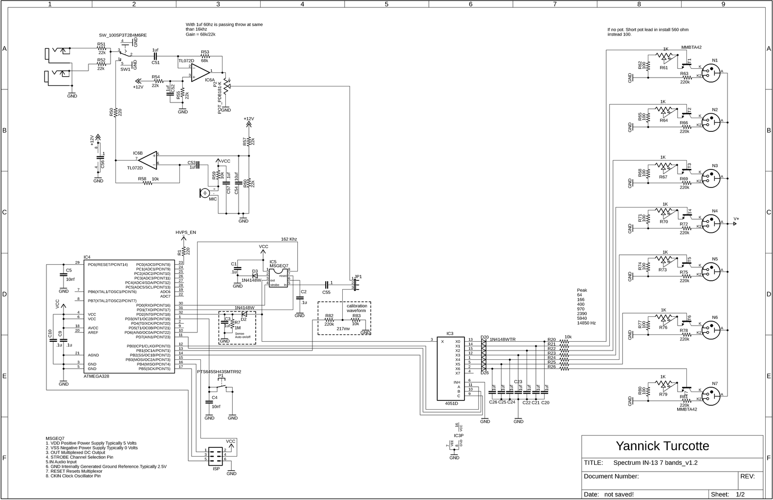
Here is the main schematic.
Line in and mic are entering in a TL072, it's a low noise fet op-amp. Very common part. 1 stage for line and 2 stages for the microphone. R58 and R53 are gain resistors.
The sound goes into the MSGEQ7. This chip split the sound into 7 frequency band. The seven frequencies are peak detected and multiplexed to the output to provide a DC representation of the amplitude of each band. more detail at next below.
After come the cd4051 demultiplexer. This part split each peak to the corresponding output pin with uC help.
0,6v was loosed by D20 to D26. To fix this, I added D3. This way the cd4051 input floor is 0,6v higher and the tubes are most responding.
Ready to enter in a high voltage base transistor to be display on the IN-13
uC job is to send data to the cd4051 to demultiplex. It can send the band left to right or right to left as per jumper setting.
uC turn on the HVPS when interrupt 0 (INT0) is trigged. If INT0 is low for around 2 minutes, uC shutdown the HVPS.
uC can output 7 frequencies (square wave) on PB1 to do a calibration of all 7 tubes. Jumper need to be switch in proper way to send the frequency to the op-amp.
uC is also providing the MGGEQ7 running frequency on PD6
The push Button is to enter in calibration mode at power on. In this mode, the push button is changing the output config frequency on each tube. The direction depend of the jumper.
Step 7: MSGEQ7


The MSGEQ7 is a CMOS chip that divides the audio spectrum into seven bands. It's a hardware FFT.
This is the datasheet. I had never used this chip before. So i did some test to learn how to handle it.
On the scope you see the beginning of reset waveform (picture 1)
Strobe is on Atmega PD0, blue waveform
Reset is on PD1, yellow waveform
Purple waveform is the output on the MSGEQ7 pin 3
Click on the picture. You will read some informations in the squares.
As per datasheet, Output Settling Time should be at least 36 us. As you can see on picture it's less than that. Datasheet is very conservative. On the picture you are seeing strobe at 20us (ts is 18 min) and tss (strobe to strobe) should be 72us min. So i choose a 52us resting time. total 20+52= 72us tss
Good to know:
On pin 8, (CKIN Clock Oscillator Pin) we must add a 200k and a 33pf to provide an oscillator of 165 kHz.
Another way I'm using, not in datasheet, is to provide 165 kHz by external instead rc method. I programmed the uC timer 0 to output the right frequency. Mode 2, clear Timer on Compare Match (CTC) Mode.
165 khz=8mhz/(2xocra) OCRA=24.24 so 24 or 0x18 Hex
Fout = 8mhz/(2x24) Fout = 160 Khz. Will be just fine.
I have tested both for fun. External and Internal oscillator method are working fine. External is more accurate and handy to fine tune by software the MSGEQ7.
Also we could add another MSGEQ7. Adjust and provide 2 different frequencies to do a 10 or 14 bar graph instead of 7.
Step 8: Prototyping
You can watch here the device in development on prototyping board. Line in input was used.
Step 9: Gerber File

You can download the gerber file with the link below:
It's only one zip file.
You can slide or open the file with the pcbway online viewer. With this you will have a very good idea on how your pcb will look like.
With the same file you can order the pcb from a manufacturer. On my side I used PCBWAY.COM
Always had excellent result with their product and service. I used them for all my other instructable project. Never have an issue so I can recommend their service without hesitation.
Do not forget to order also the stencil if you what to solder the components with solder paste. More info at step 11.
Step 10: Holder Tube

Holder stl, center tube and caps (3d printed)
In this fil you have the holder, the legs and the cap for acrylic tube and the o-ring for the in-13. Those o-rings secure the tube in the middle of the acrylic tube.
The acrylic tube come from ebay. 15mm large x 2mm thick x 165mm height.
Look to order 15mm OD, 2mm W, 11mm ID.
Step 11: Time to Solder


Normally I do it manually. But this time I ordered a stencil.
With masking tape, we align the stencil and the PCB. We add some solder paste and slowly, with an old credit card or rule, we push the paste in the stencil hole.
We remove the stencil, and carefully put all surface mount parts on the paste.
Last step is to use hot air gun to solder the parts.
On the pictures, we can see the stencil, the solder paste applied, the parts installed and soldered.
At the end, we can solder the through hole component.
Step 12: Controller Programming
This is a easy part. But could be the worst if you never did this before.
The source code is on my github Here.
You can install Atmel studio to modify the code if you what to. Or you can simply use the compiled file in the debug folder. Named Spectrum analyseur MSGEQ7.hex
In addition, you must send the right fuse but. On a brand new uC, the default clock is only 1Mhz. You need to do this to have your uC running at 8Mhz.
Fusebits are Low: 0xE2 High: 0xD9
In short, send the hex file and program the fusebits.
The simplest way is to buy an USBAPS, install the driver and run the batch file I create here.
If you have this question on the extend fusebit. Just respond NO.
quote from avrdude (batch file)
avrdude: verifying ...
avrdude: verification error, first mismatch at byte 0x0000
0xf7 != 0xff
avrdude: verification error; content mismatch
avrdude: safemode: efuse changed! Was ff, and is now f7
Would you like this fuse to be changed back? [y/n] n
avrdude: safemode: Fuses OK (E:FF, H:D9, L:E2)
avrdude done. Thank you.
Step 13: A Short Demo and How to Adjust the Tube
To adjust the tube, move the JP1 jumper. This connect the uC to the op-amp input second stage.
By holding dong the push button and connecting the power. uC enter to programming mode.
uC is sending a real square wave frequency to the op-amp.
Tube Peak are exactly at:
64 Hz, 166 Hz, 400 Hz, 970 Hz, 2390 Hz, 5940 Hz, 14850 Hz
Depending of the reverse mode jumper. 64 Hz will be at left (normal) or right.
To get out of the programming mode just power off and normally. Do not forget to put the jumper back.
Step 14: Some Pictures and a Test Video


