Introduction: Automated Arduino Controlled Smartphone 360° Photography Turntable
This instructable has full instructions to build a 360°, fully automated smartphone photography turntable. It uses an Arduino based controller to automate the rotation of a stepper motor driven turntable and an integrated Bluetooth camera shutter remote. It was built to help take product photos and videos of jewellery in our Etsy Shop.
The design is housed in a custom 3d Printed enclosure. It allows various parameters to be changed on the fly through a simple menu system, using a front panel OLED display and rotary encoder.
The turntable supports two modes, video and photo. In photo mode the turntable will rotate a chosen angle divided into a predefined number of steps. After each rotation step the turntable will pause and the smartphone camera will be triggered by an integrated Bluetooth remote. In video mode the turntable will smoothly rotate a chosen angle and the smartphone video function will be started and stopped by the Bluetooth remote. Direction and rotation speed can also be changed using the menu system.
The videos below are two examples of the turntable in action. In both cases a small, circular mirror was placed on the turntable. In the first example the turntable is operating in video mode. In the second case the turntable is operating in photo mode and the individual photos have been combined to create a stop motion effect video.
Supplies
Electronic Parts
- Arduino Nano Every
- EasyDriver stepper motor driver
- KY-040 rotary encoder (ebay or Amazon)
- Nema 17 stepper motor (750mA or less)
- OLED display module, white or blue, I2C, 0.96" 128x64 (Amazon).
- Bluetooth selfie remote control for smartphone camera shutter (ebay or Amazon)
- Prototyping board (eg. Bud Industries P/N: EXN-23402-PCB from DigiKey)
- Hookup wire (eg. these 20cm long F-F ones from the Arduino store)
- 2 x 15-pin 2.54mm female socket (for Arduino Nano)
- 2 x 40-pin 2.54mm header (for EasyDriver and connectors)
- 5.5mm x 2.1mm chassis mount DC power jack
- AC/DC adaptor supporting 12V @2A with 5.5mm x 2.1mm plug
Other Hardware (for assembly of 3d printed case)
- 12 x knurled M4 inserts (8mm long)
- 12 x M4 x 10mm countersink screws
- 4 x M3 x 10mm countersink screws
- 4 x M3 x 8mm pan head screws
- 4 x M3 split ring washers
- 3" square Lazy Susan turntable bearings / swivel plate
- 4 x adhesive rubber feet
- Adhesive tape
Tools, etc.
- Access to 3D printer
- Soldering iron
- Hot glue gun
- Screwdrivers
- Craft knife
- Ruler
- Safety glasses
- Drill (+3.5mm drill bit)
Useful but Optional
- Multimeter (for basic voltage and continuity tests)
- Small round needle file or deburring tool (to enlarge some 3d printed holes if too small)
Step 1: Electronic Design
Here is the circuit diagram for the turntable controller. At its centre is the Arduino Nano Every Board, which houses the project code and controls all operations. For detailed instructions about how to wire this circuit up using a prototyping board refer to the following pdf file.
Step 2: 3D Print the Case
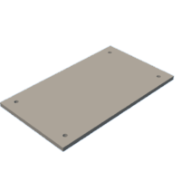
Download the stl files below (also available on Thingiverse) and slice and print on a 3D printer. Note: print two of the Stepper Motor Support files and one of every other stl file.
By choosing suitable orientation on the 3D print bed all of the files can all be printed without supports.
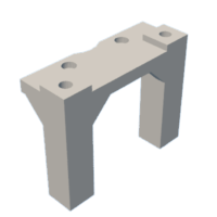
Step 3: Attach Stepper Motor Supports
The following parts are required for this step:
- 2 x 3d printed Stepper Motor Supports
- Nema 17 stepper motor
- 8 x knurled M4 inserts (8mm long)
- 4 x M4 x 10mm countersink screws
- 4 x M3 x 8mm pan head screws
- 4 x M3 split ring washers
- 3" square Lazy Susan turntable bearings / swivel plate
Using the end of a heated soldering iron insert the 8 knurled M4 inserts into the corresponding holes in the Stepper Motor Supports. Pay attention to ensure that they are inserted as straight as possible
Using the 4 x M3 x 8mm pan head screws and split ring washers secure the Stepper Motor Supports to the top of the stepper motor.
Using the 4 x M4 x 10mm countersink screws attach the Lazy Susan turntable bearings to the Stepper Motor Supports, above the stepper motor.
Step 4: Attach Turntable to Stepper Motor
The following parts are required for this step:
- Stepper Motor Assembly (from previous step)
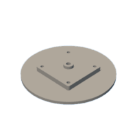
- 3D Printed Turntable Platter
- 4 x knurled M4 inserts (8mm long)
- 4 x M4 x 10mm countersink screws
- Hot glue gun (optional, alternatives described below)
Using the end of a heated soldering iron insert the 4 knurled M4 inserts into the corresponding holes in the 3D Printed Turntable Platter. Pay attention to ensure that they are inserted as straight as possible.
Apply some hot melt glue (Sugru or a silicone adhesive would also work, but would take longer before being usable) to the centre hole of the platter. Quickly, while the glue is still soft, push the stepper motor shaft into the hole, ensuring the fixing holes of the top Lazy Susan align with the corresponding mounting holes in the Turntable platter.
Note: the stepper motor you use should have a max current rating of 750mA or less to ensure that the EasyDriver stepper motor can drive it without stalling.
Using the 4 x M4 x 10mm countersink screws attach the Stepper Motor Assembly to the Turntable Platter.
Note: the Lazy Susan turntable bearings are typically very cheaply manufactured and any slight distortion causes them to start to bind. We found that even though all the M4 inserts looked to have gone in straight the bearing plate became much more difficult to turn after being screwed to the supports. This binding would have been difficult for the low current stepper motor to overcome. Our solution was to enlarge the mounting holes in the Lazy Susan metalwork with a drill (being very careful to wrap the bearings whilst drilling to avoid swarf getting in). Also avoid overtightening, as this can cause the flimsy metalwork to distort.
Step 5: Add Power Connector to Base
The following parts are required for this step:
- 3D Printed Turntable Base
- 5.5mm x 2.1mm chassis mount DC power jack
- Hookup wire (ideally black and red to correctly identify voltage polarity)
Connect 2 x red hookup wires to the centre pin terminal of the DC jack
Connect 2 x black hookup wires to the sleeve terminal of the DC jack
For our assembly we terminated the ends of the hookup wires with Molex KK series crimp terminals and connectors for convenient connection to the headers soldered onto the prototyping board in step 1. The recommended alternative to this is to use Female-Female Jumper wires for the wire links so that the unattached end of each wire is terminated in a single socket connector. These will fit cleanly next to each other on any standard-pitch 0.1" (2.54mm) header.
Screw DC Jack through the hole in the base
Step 6: Program Arduino Nano Every
Download the sourcecode from Github:
https://github.com/Fabshed/FS_photography_turntable
Download and install the latest version of the Arduino IDE:
https://www.arduino.cc/en/software
Download / install the additional third party libraries specified in the readme.md file downloaded with the sourcecode from Github.
Connect the Arduino Nano to your PC with a micro USB cable, select the appropriate board (Arduino Nano Every) and port in the Arduino IDE. Then compile and upload the code.
Note: The software and prototype board was designed around an Arduino Nano Every but it should be possible to run on any Arduino Nano with with minimal changes.
There are lots of comments in the code so hopefully you should be able to modify to suit your needs.
Step 7: Fit Rotary Encoder and OLED to Front Cover
The following parts are required for this step:
- 3D Printed Front Cover
- KY-040 rotary encoder (ebay or Amazon)
- OLED display module, white or blue, I2C, 0.96" 128x64 (Amazon)
- Hookup wire (eg. these 20cm long F-F ones from the Arduino store)
Push the shaft of the rotary encoder through the front cover and secure with the supplied nut, in the orientation shown.
Before fitting the OLED look at the silk screen markings labelling its pins and write them down.Different models can have these pins in a a defferent order. For the OLED to fit properly it should be one of the models with oval mounting holes such as this one from Amazon.co.uk:
https://www.amazon.co.uk/Display-Adafruit-Arduino-Beaglebones-Raspberry/dp/B07JN2NHT4
Fit the OLED over the alignment lugs on the front panel in the orientation shown. Using the tip of a heated soldering iron slightly melt these alignment lugs so that they hold the OLED securely in place.
Connected coloured hookup wires to the rotary encode and OLED as shown. It is recommended to use the colours shown in the photos as these are the colours we used in the prototype board instructions and it will simplify followiing the final cabling instructions at the end of this document, The connectivity instructions will be very detailed, however, so do not worry if you cannot match the colours. For the OLED connections please make sure you connect according to the pinout of your module rather than assuming it is the same as the one we used, There seem to be two common pinouts and the ground and +3V3 power pins are opposite for these two pinouts. Accidentally reversing the power connections is likely to damage your display.
Step 8: Prepare Bluetooth Selfie Remote Shutter Clicker
The flollowing parts are required for this step:
- Bluetooth selfie remote control for smartphone camera shutter (ebay or Amazon)
- Hookup wire (eg. these 20cm long F-F ones from the Arduino store)
- Hot glue gun (or double sided adhesive foam)
You will need to source a low cost Bluetooth Selfie Remote Shutter Clicker. It only needs to be a simple one button version, powered by a 3V CR3032 button cell. We bought the following one from Amazon.co.uk:
https://www.amazon.co.uk/gp/product/B09DK5FG5G
and it is also available from AliExpress:
https:www.aliexpress.com/item/33017967218.html
Most similar models will also be usable but there will be a certain amount of reverse engineering to work out exactly where to solder the connecting wires if a different one is used.If you can use the same model you will only need to copy the connections we made.
Open up the plastic case of the remote by inserting a flat bladed screwdriver into the joining seam and twisting. The case and battery Cell will not be used for this project. It the Selfie Remote has an on off button set it to 'On' before dismantling.
Locate the positive battery terminal on the PCB (usually marked with a '+') and solder a red hookup wire to it. This will be connected to +3V in a later step.
Locate the negative battery terninal on the PCB (usually marked with a '-') and solder a black hookup wire to it. This will be connected to Ground in a later step.
Locate the pushbutton used to make the connected smartphone take a picture. At least one pad of the button will likely be connected to Ground. Another pad of the button will likely have a track connected to it that will also connect to the main integrated circuit on the PCB. Assuming that this is similar to the Selfie Remote we used, every time the button is pressed this pin is shorted to ground, triggering the camera. Solder an orange hookup wire to this pad,
Using hot glue or double sided adhesive foam stick the remote to the front cover, between the rotarty encoder and OLED display in the orientation shown
Step 9: Connect Up and Test
The following parts are required for this step:
- Multimeter for simple voltage and continuity checks (optional but very useful)
- 3D Printed Base with 12V DCIN cable fitted
- 3D Printed Front Cover with rotary encoder, OLED and Bluetooth Selfie remote installed
- Assembled prototype board (with Arduino and EasyDriver boards)
Now is a good time to connect up all the cables and check that everything is working as required before finally screwing the electronics into the enclosure. Check your prototype board carefully against the schematic, looking for inadvertant shorts and connectivity errors. If you have a multimeter check that none of the power rails (3V3, 5V and 12V DCin) are shorted to ground or each other.
First connect the 12V DCin cable (that is fitted in the 3D Printed Base) to the appropriate connector on the assembled prototype board. Before applying power verify that +12V is connected to the centre pin of the DC Jack and that the chosen 12V AC/DC adaptor also has +12V connected to its centre pin. If all is as expected plug in the power and switch on. You should see an illuminated Green LED on the Arduino board and a Red LED on the EasyDriver board. If there any problems at this stage it is really just a case of checking that 12V gets to the correct pins of the Arduino and EasyDriver board and that GND is also connected to the correct pins.
Once this step is working, unplug the power and continue with the cabling. Connect the cables from the rotary encoder, OLED display and Bluetooth selfie remote to the appropriate connectors on the prototype board. Pay special attention to the OLED display interface which could have the interface pins in a different order to the one I used if a different model is used.
If everything is properly connected the OLED display should display a software version when powered and the top level of the menu system, with the rotary encoder allowing menu navigation and selection. Using a smartphone it should be possible to find and connect to the selfie remote over Bluetooth.
Step 10: Connect Stepper Motor
The following parts are required for this step:
- Cabled up electronics from last step
- Stepper motor assembly
- Soldering iron
You will need to determine the wire pairs for each coil of the stepper motor you are using. If you have the data sheet for the motor then this information will be provided. In the absence of a data sheet a multimeter can be used. Take one wire and check its resistance against each of the three remaining wires. Whichever wire shows the lowest resistance against the first wire is its pair mate. The remaining two wires are also a pair.
Once you have determined the coil wire pairs, you will need to attach them to the EasyDriver board. The first coil pair should be soldered onto the Coil A+ / Coil A- interface pins (on the reverse of the protoyping board). The second coil should be soldered to the Coil B+ /Coil B- interface pins (again on the reverse of the protoyping board). You can try soldering a pin header to the interface pins if the stepper motor has a connector on the end of its cable, otherwise solder the stepper wires directly to the interface pins. There is no polarity on the coils, so you cannot plug a coil in backwards. If, during use, the motor turns opposite to the currently selected Clockwise / Counter Clockwise parameter, simply swap the pairs (or change the direction in the software).
Note: Do not connect or disconnect the motor while the Easy Driver is powered. If any of the motor wires comes loose while power is applied, the driver can be damaged.
If the motor skips steps then you may have to tweak the adjustable current controller on the board. The EasyDriver supports motor currents from 150mA to 750mA by turning the onboard potentiometer.
More current equals more torque, more heat, less speed and more motor noise
Less current equals less torque, less heat, more speed and less noise
The recommended way to adjust is to turn the current all the way down to minimum. Then turn the potentiometer slowly to the point where the motor no longer skips steps. Selecting run with it set to video mode, the highest speed and the largest angle is the best way to judge this. The faster the motor is set to move, the higher the risk of skipping steps, so doing the adjustments at the highest speed is recommended.
Step 11: Finish Assembly
The following parts are required for this step:
- Cabled up electronics
- 4 x M3 x 10mm countersink screws
- 4 x M3 x 8mm pan head screws
- 4 x M4 x 10mm countersink screws
- 4 x adhesive rubber feet
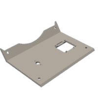
First secure the prototyping board to the angled mounting stand in the base using the 4 x M3 x 8mm pan head screws. Route the cables from the back to the front as shown in the photo.
Now fit the front cover to the base using 4 x M3 x 10mm countersink screws.
Now fit the stepper motor assembly into the base and secure with 4 x M4 x 10mm countersink screws. Ensure no cables are trapped.
Finally fit 4 x rubber feet to the base.
The turntable is now fully assembled !
Step 12: Using and Further Thoughts
If everything has been properly connected, the turntable is very simple to use. When it is switched on just make sure your smartphone is connected to the remote selfie clicker using Bluetooth.
Place the object you want to photo / video on the centre of the platter. Set the mode to video or photo. For photo mode also set the number of still photos you want to take (up to 40). Then choose the angle (5 - 720 degrees) and the speed (set lower for smoother, more reliable operation).
Set up your smartphone to take the video (ideally on a tripod) and select run. The turntable will spin and the camera / video will be automatically controlled according to the mode, starting or stopping the video or taking a selected number of still photos.
Tip: Try adding a lightweight, round acrylic mirror on the platter, beneath the object you are photographing.
By replacing the Bluetooth remote control with an IR transmitter or a connector it should be easy to modify the unit to control other cameras.
Please contact us if you have any questions.


![Tim's Mechanical Spider Leg [LU9685-20CU]](https://content.instructables.com/FFB/5R4I/LVKZ6G6R/FFB5R4ILVKZ6G6R.png?auto=webp&crop=1.2%3A1&frame=1&width=306)


