Introduction: Automation Using NodeMCU
How to control relay using web server.
Step 1: Components
Hardware
- NodeMCU Development board
- Relay
- USB cable
Software
- Arduino IDE
Step 2: Components Detail
What is a Relay
Relay is an electromagnetic device which is used to isolate two circuits electrically and connect them magnetically. They are very useful devices and allow one circuit to switch another one while they are completely separate. They are often used to interface an electronic circuit (working at a low voltage) to an electrical circuit which works at very high voltage. For example, a relay can make a 5V DC battery circuit to switch a 230V AC mains circuit.
How it works


A relay switch can be divided into two parts: input and output. The input section has a coil which generates magnetic field when a small voltage from an electronic circuit is applied to it. This voltage is called the operating voltage. Commonly used relays are available in different configuration of operating voltages like 6V, 9V, 12V, 24V etc. The output section consists of contactors which connect or disconnect mechanically. In a basic relay there are three contactors: normally open (NO), normally closed (NC) and common (COM). At no input state, the COM is connected to NC. When the operating voltage is applied the relay coil gets energized and the COM changes contact to NO. Different relay configurations are available like SPST, SPDT, DPDT etc, which have different number of changeover contacts. By using proper combination of contactors, the electrical circuit can be switched on and off. Get inner details about structure of a relay switch.
The COM terminal is the common terminal. If the COIL terminals are energized with the rated voltage, the COM and the NO terminals have continuity. If the COIL terminals are not energized, then the COM and the NO terminals have no continuity.
The NC terminal is the Normally Closed terminal. It is the terminal that can be powered on even if the relay doesn't receive any or sufficient voltage to operate.
The NO terminal is the Normally Open terminal. It is the terminal where you place the output that you want on when the relay receives its rated voltage. If there is no voltage to the COIL terminals or insufficient voltage, the output is open and receives no voltage. When the COIL terminals receive the rated voltage or a little under, the NO terminal receives sufficient voltage and can turn on the device on the output.
What is NodeMCU
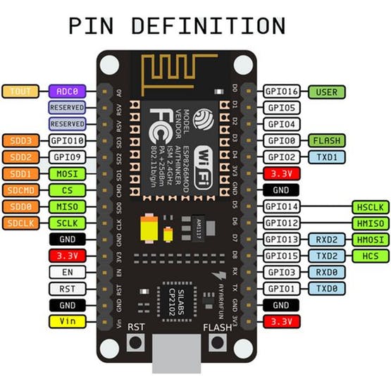
NodeMCU is an open source IoT platform.It includes firmware which runs on the ESP8266Wi-FiSoC from Espressif Systems and hardware which is based on the ESP-12 module.

How to program NodeMCU with Arduino IDE
To connect NodeMCU to pc serially you have to install cp2102 driver. Once you installed driver, connect NodeMCU with pc ,open Arduino IDE and select board NodeMCU 1.0 and select port. After that upload the code.
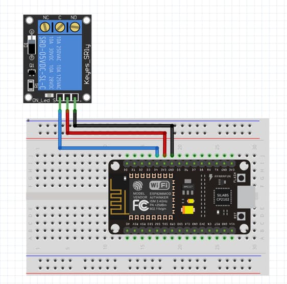
How to connect NodeMCU with relay
Here, I only connected one connection. You can even connect voltage pin to Vin of NodeMCU instead of 3.3V.

Step 3: Setup NodeMCU in Arduino IDE
Step 1
Open Arduino IDE.Then go to File => Preference

Step 2
In Additional Boards Manager, copy and paste the URL and click ok:
http://arduino.esp8266.com/stable/package_esp8266c...


Step 3
Open Board Manager by going to Tools => Board => Boards Manger.

Step 4
Open Boards Manager and search for nodemcu.

Step 5
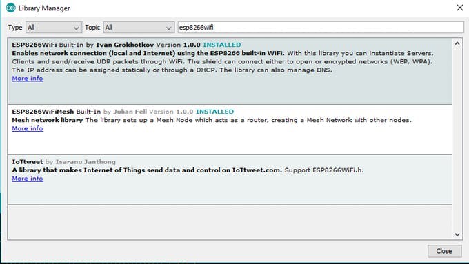
After that download ESP8266WiFi library . Open library Manager: Sketch => Include library => Manage Libraries

Search for ESP8266WiFi library

Step 6
Select Board and Port.


Step 4: Program
Attachments
Step 5: Result


Participated in the
IoT Challenge


