Introduction: Boat Sculpture
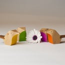
I'm in the mood to create a wood sculpture? But maybe as a decor item that's both artistic and functional at the same time? Every day I look at Pinterest for images that are interesting and screen capture those. There's 3 such images above, the first a sculpture by Debra Fritts titled "Prayers for the Children", The second, a beautiful photo by Osman Rana - Unsplash. Lastly a painted river stone, unkown artist?
I thought about creating an abstract sculpture/serving platter, as a compilation of thoughts? You know, a boat with a headpiece and an awesome textured deck, of course? A centre piece platter to display..... whatever?
I'm going to use hardwood 26mm (1") thick as my building canvas. I want to keep the boat width fairly wide in comparison to the length to show case off the deck texture. Therefore the boat hull will be 200mm (8") long x 140mm (5-1/2") wide, be carved with a CNC from top and bottom. A head piece nominally 32mm (1-1/4") high will sit atop the foredeck. The head piece will be carved using an imported .obj file.
Supplies
An imported 3D file of a funky Bust (Head piece)
Fusion 360
CNC machine, 6mm (1/4") & 3.175mm dia (1/8") flat end mill, 2mm dia ballnose mill.
Hardwood 26mm thick (1") x a minimum 240mm (9-1/2") x 213mm (8-1/2")
Step 1: Design the Hull
Using Fusion 360, create a new sketch on the XY plane, a centre rectangle 200 x 140mm. Then offset a plane 26mm higher and project the lower rectangle. Now create a sketch on the XZ plane and project the top and bottom rectangle points and draw another rectangle. Repeat for YZ plane. You've now built a sketch 'cage' to contain your model.
On the XZ plane Sketch3 draw the longitudinal profile of your boat hull using splines and straight lines. On the YZ plane Sketch4, draw a mid section profile, making sure to use CREATE ~ Project Intersect to identify the cross section of other sketch lines and points. I'll make the profile to be fairly flat bottomed for stability of the model 'on the high seas'?
Now for the rear transom. CONSTRUCT ~ Plane at Angle on the transom line. Create sketch on Plane 2 and Project the intersection points. Draw your transom profile incorporating a keel. Now we need to use F360's awesome new 3D sketch addition (2020). We need a Rail on the top perimeter to Loft. Create new sketch on XY plane. Ensure 3D Sketch is ticked on the SKETCH PALETTE. Using Fit Point Spline draw line from transom top left to mid section to Bow top point. Use the MOVE/COPY command to adjust the spline tangent handles to get to the desired profile as viewed from the TOP.
Select SURFACE mode. CREATE ~ Loft. Now I ran into trouble with F360 when I tried to loft from the transom to bow in one go. F360 didn't like my centreline Rail, something about self intersecting! Therefore I did the Loft from centreline to top rail line and used the mid plane and transom sketch splines as Rails. It worked and the hull looks pretty sexy?
Time to CREATE ~ Thicken by 3mm. You now have a Solid Body. Move back to SOLID mode from SURFACE. CREATE ~ Mirror the new Body. Then MODIFY ~ Combine the two bodies.Time to build the Transom. Select Transom sketch profile and Extrude it 3mm. You can Remove the Surface Body now. Rename Body "Hull". Almost forgot the Keel? Create new Sketch on XZ plane, project body and previous geometry. Now because the bottom of the hull is curved the Extrusion will have an issue joining to the Hull. Increase the height of the spline line by 1mm. Extrude symmetrically 3mm each way. MODIFY - Fillet where keel abutts the hull 2mm rad.
Upon reviewing the body, I notice a slight impediment at the top corner junctions of Transom and Hull. There's only 0.5mm in it so easily sanded out later. Now we need a deck? Go back to SURFACE and Loft between top rail outer edges. Thicken this Loft by 3mm. Remove previous Loft Surface body.
Step 2: Deck Texture
I want to texture the deck to a similar pattern to the above first picture. Offset a Plane 40mm above XY plane. Then Create Sketch on that plane and Project the inner rails. Sketch a Fish as shown. Now Edit Sketch right click sketch Copy and Paste that fish, then re-orientate and resize within the boundaries of the deck. Repeat until all your space is filled with fish. Stop Sketch, select the fish and Extrude down into the deck of the boat. Now select all the new fish bodies and Split Body using the deck face as cutting tool. This now creates twice as many fish bodies, those above the deck, and those below. Remove, not Delete, those bodies above the deck. Now select the fish body faces outlined on the deck surface and Press Pull those out 2mm.
There you have it, a nicely fish laden deck! However I've made a slight error? By extruding the fish up 2 mm, the model is higher than my wood at 26mm high. Also on close inspection part of the thickened side rail impedes the boundary too! OK time to scale the body down 7%.
Step 3: Bow Head Piece
Time to adorn our boat with a symbolic headpiece. Over at CGTrader I found a free download, a Mayan Bust. Let's assume this guy is the patron saint of fishermen as they certainly pulled in a haul! You go INSERT - Insert Mesh. You need to turn the timeline history off to enable further work? Select Boat v5 Disable Design History.
Right click Group 34825 (my mesh import) then Mesh to BRep. You'll get a Warning that the mesh facets are too many. I ignored the message and clicked OK, it converted just fine and is now a solid body. However it's a lot of facets, so I'll retrace back to the mesh body. This time choose MESH format MODIFY ~ Reduce. Change Reduce Target to Face Count. I'll reduce from 6754 facets to 2969. Go back and right click Group 34825 (my mesh import) then Mesh to BRep. I've got a simpler shape now?
How tall is this dude? Select FRONT elevation and create sketch on XZ plane. I'll switch Capture Design History back on. Project Body and measure the height of the bust? He's only 3.5mm high from head tip to bottom of neck. (I'll ditch the stand). We'll make him 25mm high, that's a 700% increase. MODIFY Scale and upsize. Create new sketch on XZ plane again and Project Body. Draw a line at the bottom of his neck. Finish Sketch. CONSTRUCT Plane at Angle on that line. MODIFY Split Body use that plane to split Bust. Then remove redundant bits. It turns out the Bust comprises 4 parts? Combine them all. Now select the new combined body right click and Move it into position. I change the APPEARANCE of the bodies.
I'm thinking that our Bust is a little small? Rescale it 150% and reposition.
Step 4: Tabs and Pre-Manufacture
Time to think CNC carving for this sculpture. The first thought that should come to mind is securing your model? We need tabs to hold the bodies in place whilst machining as well as surrounding acreage to secure with clamps? The acreage is simple, just have a piece of wood big enough! In this instance I'm using a piece of Karri 240 x 213 x 26mm. Tabs are a little harder, you need enough to hold the body but easy to cut and sand off later. For the Bust I'll have one tab on the bottom. For the Hull, I'll use 5 tabs. Create a new sketch on XY plane and Project your bodies. Notice I've moved the Bust to sit flat?
Start drawing centre rectangles around the body outline. Keep them all 10mm wide by a generous height (> 12mm). The consideration here is the dia of the tool you're using to cut out the contour? In my case 6mm (1/4") dia. It'll become clearer why, later? MODIFY ~ Offset a 6mm line around the Hull. Now trim off the excess, as well as the surplus offset line. This is needed as a contour path for your tool. The Bust gets a 3.175mm (1/8") offset. Now extrude each tab as an offset to be 4mm thick. Switch your Bodies back on and lift each tab extrusion up to be nearly flush with top rail at highest point (for Hull) and middle of the Bust neck. You can see the tab for the Bust in the pic. It's not quite centred. I'll go back to the tab sketch and make it a bit wider. I then used the bottom face of the Bust neck to Split the tab body, to remove the excess projections. Remove the redundant body and then Combine the tab to the Bust body. There's a pic above showing the Hull and Bust with tabs attached.
Almost ready for the Manufacture stage, but first you need to create a new sketch on XY plane and project the new profile with tabs added. We need this sketch to tell F360 where to cutout the body contours, BUT we don't want the tool to cut around the tabs, just each side. Keep that last sketch open and switch off all other sketches. Switch on the Hull body only. Move to MANUFACTURE mode.
Step 5: MANUFACTURE
In MANUFACTURE mode select SETUP ~ New Setup. Add the size of wood your using and select the Hull as Model. Go 2D ~ 2D Contour. Select a 6mm dia tool, then hold down ALT key and select profile, ignoring the longside of each tab. Watch the youtube to see setup and simulation. Next select 3D ~ 3D Adaptive. Change tool to 3.175mm dia (1/8"). Watch video for setup. Next 3D Scallop and change tool to 2mm dia Ballnose. See video for setup.
Okay now that the top of the Hull's done, one side of Bust to do? Go through new 2DContour, but use 3.175mm dia (1/8") tool, then Adaptive and finally Scallop with 2mm ballnose. Time to flip sideways the View and do SETUP ~ New Setup. Insert same size wood dimensions, then flip Z and X axis.
As the 2D Contour was done in previous operation, proceed to 3D Adaptive using 3.175mm dia (1/8") tool. See youtube for setup. Next is 3D Scallop, see youtube for setup. Lastly there's a simulation video of the combined tool operations.
Finally, over to the Axiom CNC to machine.

Participated in the
Sculpting Challenge


