Introduction: Build a 10 Ton Hydraulic Press


More by the author:


About: general bloke type of tinkering
A press is something you dont use often in the home garage, but when you need one, nothing else will do.
I needed to straighten a bent bike axle, and after pricing one in a machinery shop ( I've bought a car for less, admittedly that was in 1984 though), I figured I could make one, I mean how hard could it be?
Pretty easy it turns out, all you need is some big bolts, heavy duty steel and a hydraulic jack, after some labour in the shape of welding, drilling, cutting and grinding, a 10 ton press appears.
Some research on the topic of presses soon revealed some aspects of design and usage functionality:
I also wanted the bottle jack to be removeable in case it was needed to do duty elsewhere.
I needed to straighten a bent bike axle, and after pricing one in a machinery shop ( I've bought a car for less, admittedly that was in 1984 though), I figured I could make one, I mean how hard could it be?
Pretty easy it turns out, all you need is some big bolts, heavy duty steel and a hydraulic jack, after some labour in the shape of welding, drilling, cutting and grinding, a 10 ton press appears.
Some research on the topic of presses soon revealed some aspects of design and usage functionality:
- Some presses had winches to raise the lower work table and had never used that function.
- Most presses in the 10 ton range had fixed hydraulic rams, no side to side movement, so everything had to be centered for it to work.
- Bench presses were limited in their use due to small size and large floor standing ones were heavy and had wasted space.
- A return spring speeded up the process and made working with the weight of a 7kg jack much easier.
- A gauge was nice to have but not a necessity.
I also wanted the bottle jack to be removeable in case it was needed to do duty elsewhere.
Step 1: Safety First

A small amount of welding will be needed on the upper and lower bottle jack brackets and also on the stabilizer feet.
Lots of grinding and cutting of the steel is involved.
The 20mm holes were drilled with a Blu-Mol bi-metal hole saw in a drill press and it flings hot shavings everywhere.
With that in mind, all the cautions regards welding apply, ie long sleeves, proper welding gloves and helmet for arc welding. Bear in mind that you can get uv burns on the neck area that isnt covered by the bottom of the helmet, especially when welding objects on the floor. Proper footgear (safety boots or at least leather shoes) while welding is also a must, its hard to get neat welds while dancing around in slip slops with hot molten metal drippings on the toes.
Its very advisable to weld outdoors due to the fumes, be very cautious of welding on gavanised metal because it releases clouds of white toxic smoke.
Its very advisable to weld outdoors due to the fumes, be very cautious of welding on gavanised metal because it releases clouds of white toxic smoke.
Lots of grinding and cutting of the steel is involved.
With that in mind, eye and hearing protection is a must. An angle grinder with a cutoff blademakes a racketwhich soon causes a ringing in the ear without proper protection, it also sprays a shower of sparks which can bouce back off nearby objects, beware the hot spark bouncing back off a wall over the top of your safety goggles, its not a fun experience.
A pair of work gloves is good insurance against a wire brush if it should slip, as well as cutting down on the vibration being transmitted to your hands.
A pair of work gloves is good insurance against a wire brush if it should slip, as well as cutting down on the vibration being transmitted to your hands.
The 20mm holes were drilled with a Blu-Mol bi-metal hole saw in a drill press and it flings hot shavings everywhere.
With that in mind, eye protection is amust, its also a caution on the outside of the blu-mol box. When the hole saw binds it can exert force on the work piece, so said work piece should be safely clamped to revent rotation.
Step 2: Parts and Tools


Tools
- arc welder
- drill press with a Blu-Mol bi-metal 20mm hole saw, recommended cutting speed is 440 rpm.
- a 115 mm angle grinder + cutoff and grinding disks
- 4 metres taper flange 100mmx50mm steel channel, (the taper flange is cheaper and stronger than the parallel flange)
- 2x 1metre side uprights
- 4 x 560mm cross bars (my 2m piece measured 2.24m so I just quartered it )
- 1.2m 30mm equal angle iron for stabilizing feet.
- 460mm cross brace
- 2x 350mm side braces
- 8 x 20mm bolts for cross members(I had 4x 20mm bolts on hand and bought 1 metre M20 allthread plus 8 M20 nuts).
- 4 x M8 bolts for the feet.
- 10 ton bottle jack.
- 1x 200mm x 100mm x 20mm for top jack bracket. (flame cut at a speciality steel shop)
- 300mm x3mm mild steel for bottom bracket.
- 1 x 300mm x 10mm rebar for top bracket return spring mounts.
- 2 x 200mm x 100mm x 20mm flame cut V-blocks. (flame cut at a speciality steel shop)
Step 3: Starting at the Bottom


Figured I'd cut and weld the foot brace once I knew that the cross members were 560mm, this resulted in the bottom foot cross brace being 460mm long, being the distance between the side posts and 350mm for the side braces seemed stable enough.
Then it occured to me that it would be easier to drill the 8mm fixing holes before I welded the cross brace on. So first I marked out holes in the brace then drilled with a 2mm pilot bit, once that was done I laid the angle iron on the side upright channel to transfer markings across.
This resulted in nicely centered holes which will only fit the corresponding foot brace.
Step 4: The Frame


That Blu-Mol bi-metal munches easily through 8mm steel and was still sharp even after 32 holes. It does leave a nasty ridge on the other side so be careful when brushing away metal shavings those ridges are plenty sharp and will be grinded down before painting.
A point to consider is that taper flange channel can result in pieces not fitting properly once assembled, the choices are to either file the mating surfaces flat or allow more clearances in the top sliding bracket.
I marked out the holes on cross members 30mm in from the edges and found that instead of the hole centers being 40mm apart(100mm width minus 60mm combined inset should have been 40mm remainder), it was actually a better fit if I made them 39mm apart when laying out the center punch marks on the side uprights.
A 2D cad file with the basic measurements has been attached.
Attachments

Step 5: Bottle Jack Brackets


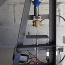
I welded a section of pipe onto the top bracket to locate the jack screw top, then attached some bent rebar for the return spring mounts when I eventually find a pair. In the meantime a pair of elastic luggage straps works well enough.
The bottom bracket was bits of scrap steel offcuts welded and bent to contain the jack base, the chain links being for the elastic cords while I look for suitable springs.
A caution on the elastics reads, dont stretch beyond 50% of original length, check often for damage, fraying etc, dont put face or body parts in path of stretched cord should it break.
Step 6: Testing


It easily bends 10mm rebar over a wheel brace, only to 90 degrees though, so I had to use fence posts and long levers to bend them in a U.
The only bottle jack mod was pressing out the original valve pin and putting in a much longer one to make it easier for finger use.
Thought it might be cool to do some die pressing but the thin pepsi can burst at the seams, thicker metal might do the trick, or possibly thinner wire than the 1.23mm stuff I used.