Introduction: Build a One-Handed Soldering Tool 2.0 | Effortless Soldering With Only One Hand
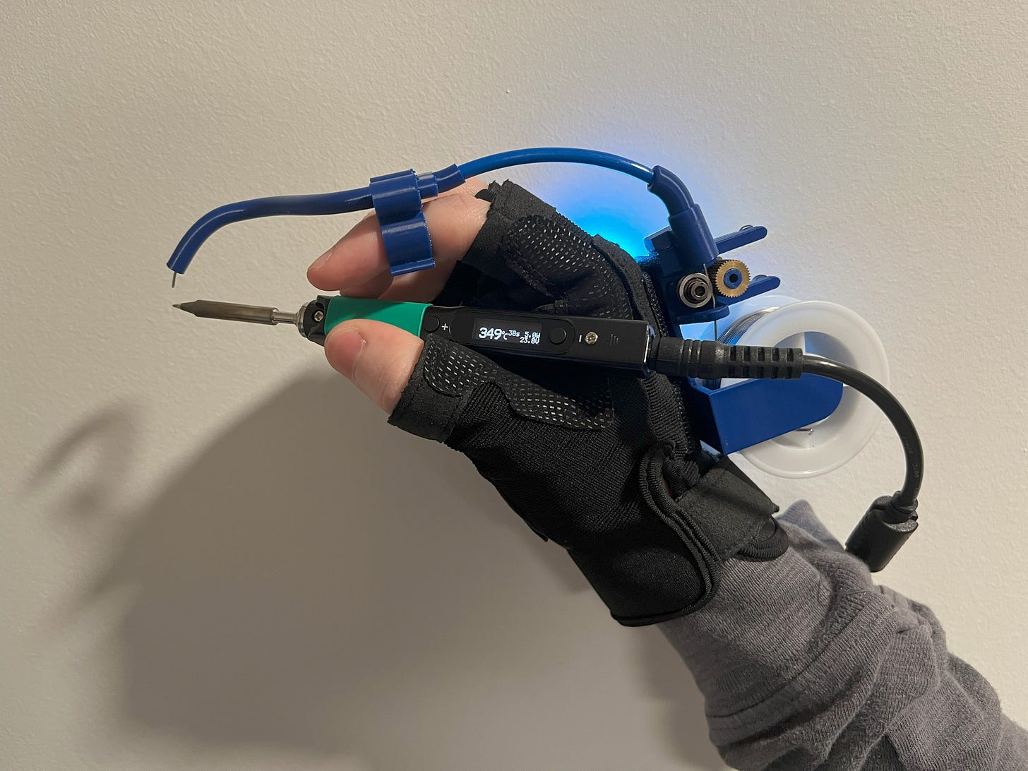
In this project, I will show you how to build a neat soldering glove attachment that allows you to effortlessly bond wires while only utilizing one hand for both the solder and soldering iron.
For the best quality read, check out this article on my homepage here. If there's a pop-up, just simply click dismiss at the bottom. Also, don't forget to subscribe for free to support my work! :)
Step 1:
A Quick Preview
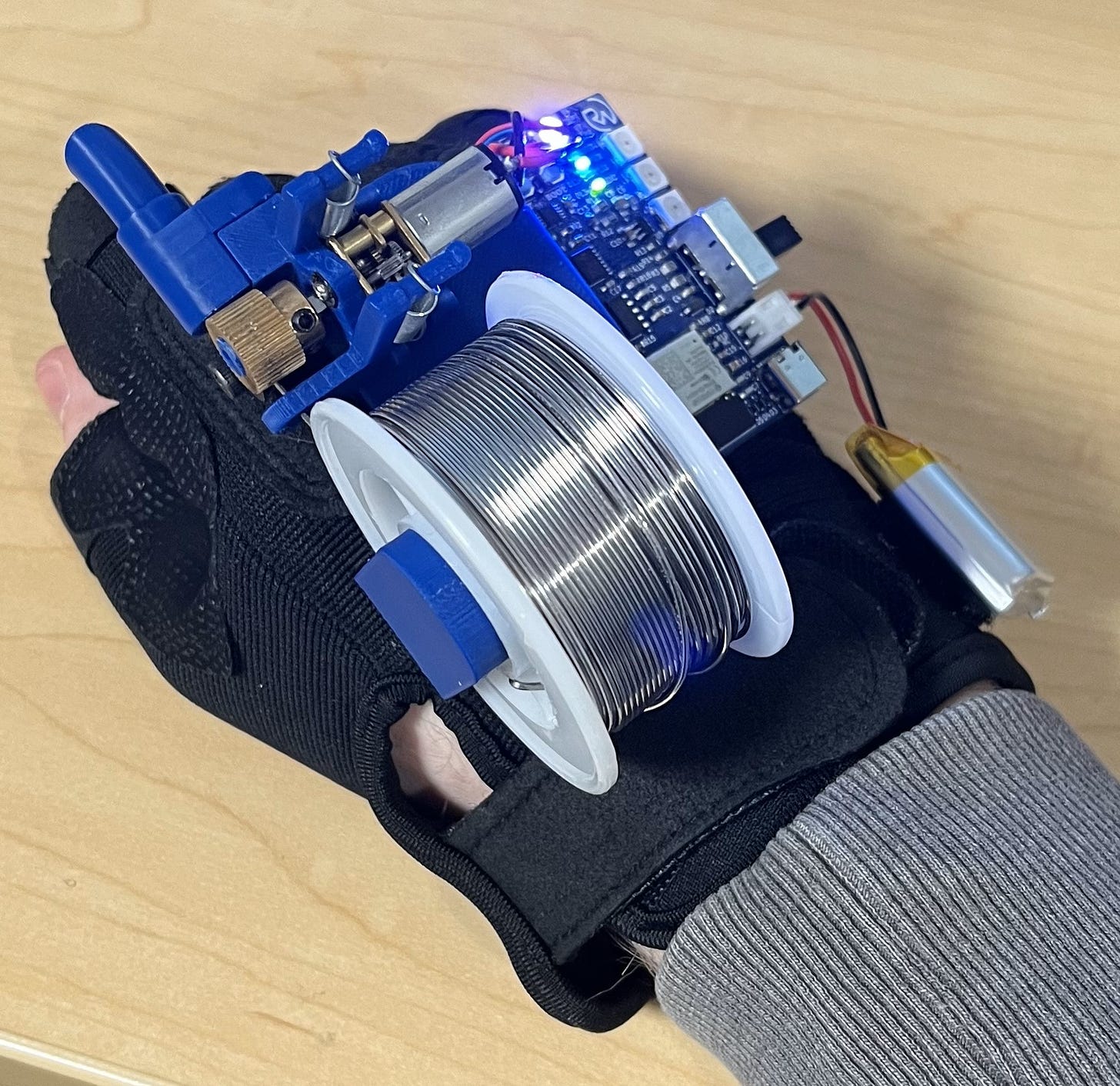
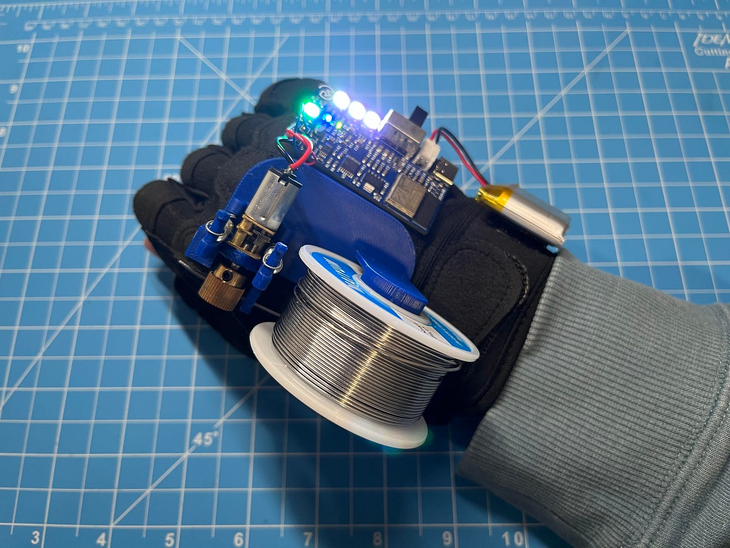
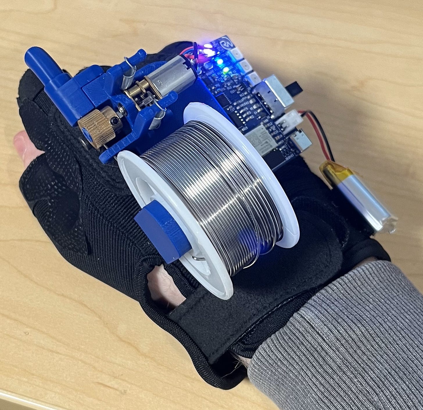
This is the long-awaited Solder Sustainer v2, the predecessor of the well-known Solder Sustainer that I built and designed back in July 2023. This device will allow you to solder with precision while only utilizing one hand, freeing up your other to hold whatever wire or component you are trying to solder. I don’t think I’ve ever been able to solder things so easily! (If you’re not totally sure what soldering is, check out this link.)
Here is a preview of the final project :)
(Yes, a left-handed version is also available!)
Step 2:
Units are also available for sale on roboticworx.shop!
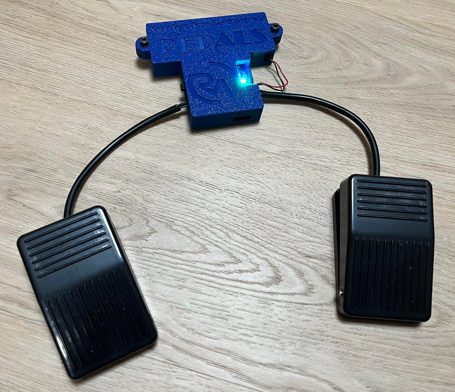
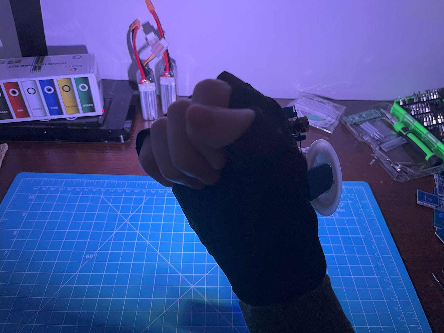
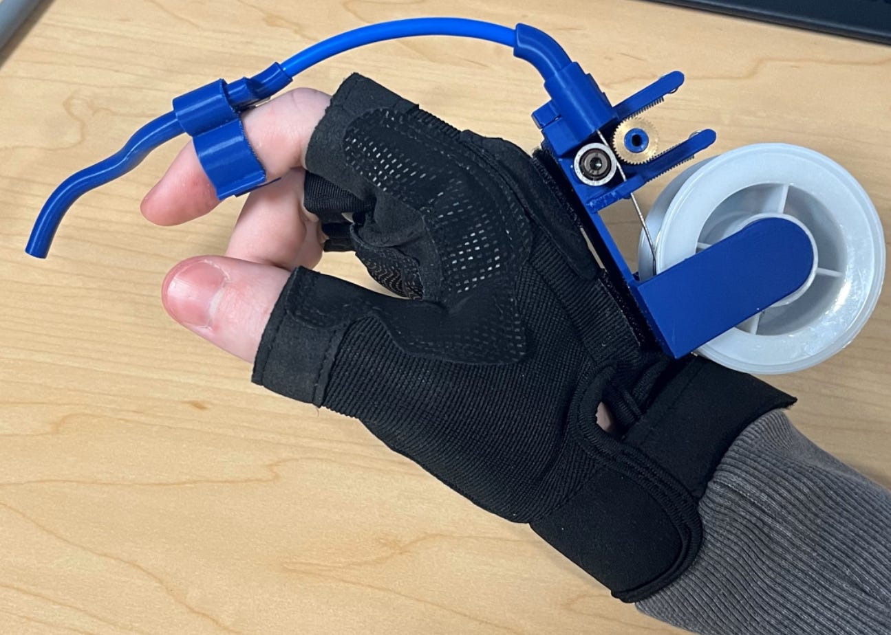
Being that the solder guide is around your finger, it allows you to direct the solder more accurately so that you can solder things with the same precision that you normally would with two hands! You also don’t need to press a button on the iron to extrude anymore (like the v1), since the extrusion and retraction tasks are being handled by two wireless foot pedals.
*This too has a battery color indicator and is rechargeable via a USB-C!
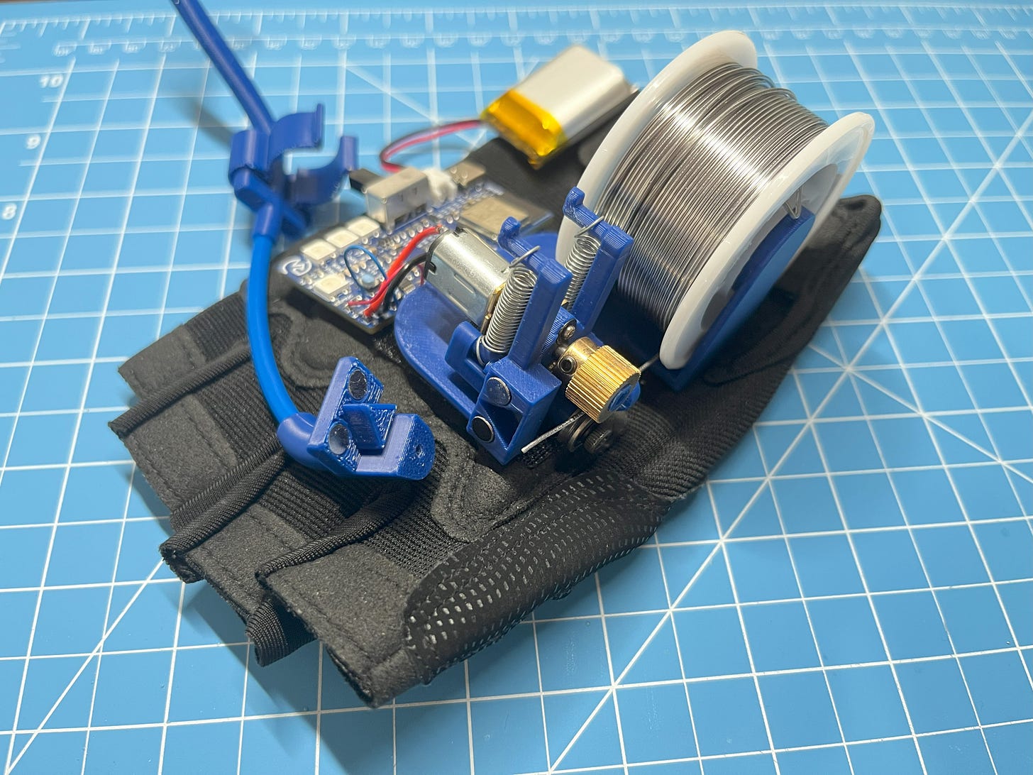
As seen in the video, the guide is also completely detachable using powerful Neodymium magnets so that you can easily switch it out based on the task you’re trying to accomplish.
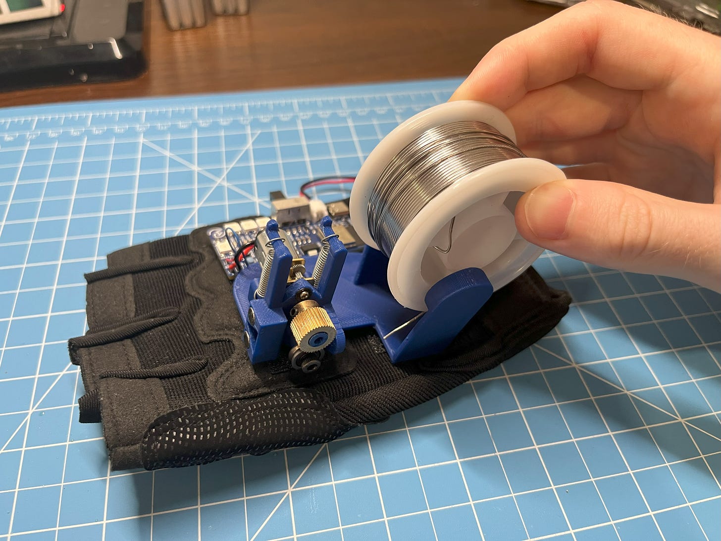
Another improvement the v2 has over the original is that the solder spool is now easily detachable as well. The spool holder is designed to be able to be flexed, so now all you have to do is pull the holder back, pop the spool out, and snap in a new one whenever you need a refill!
The Solder Sustainer v2 is also compatible with any soldering iron! Whether you're using a mini iron like me or a generic one, there are multiple solder guides available for full compatibility.
Of course, you probably also saw the three, awesome, high-powered soldering lights that can be activated when pressing down on both wireless foot pedals! These can also be configured for other colors based on your preferences (explained in programming).
It should also be noted that these lights are at only 78% power to preserve battery life. They can get even brighter if you want them to!
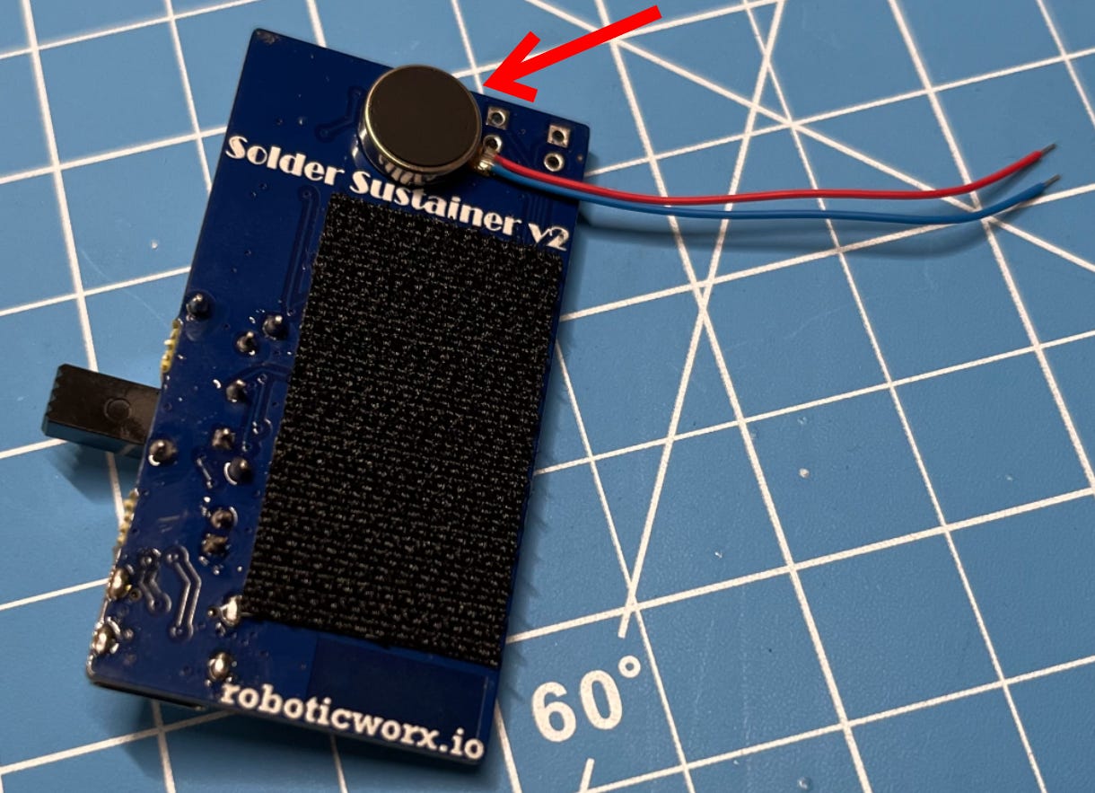
The last feature the v2 has over the original is that it also includes a haptic feedback motor. This buzzes on start-up to inform you if everything is working as it should. Pretty cool!
Hopefully, now you want one for yourself. Luckily, this is a completely open-source project! But first, let me explain how it works.
Looking for a specific section? Jump to it using these links:
Working Concept | Understanding the Hardware | Building the Boards | Building a Version 3 | Assembly | Programming | BOM (Bill of Materials)
Working Concept
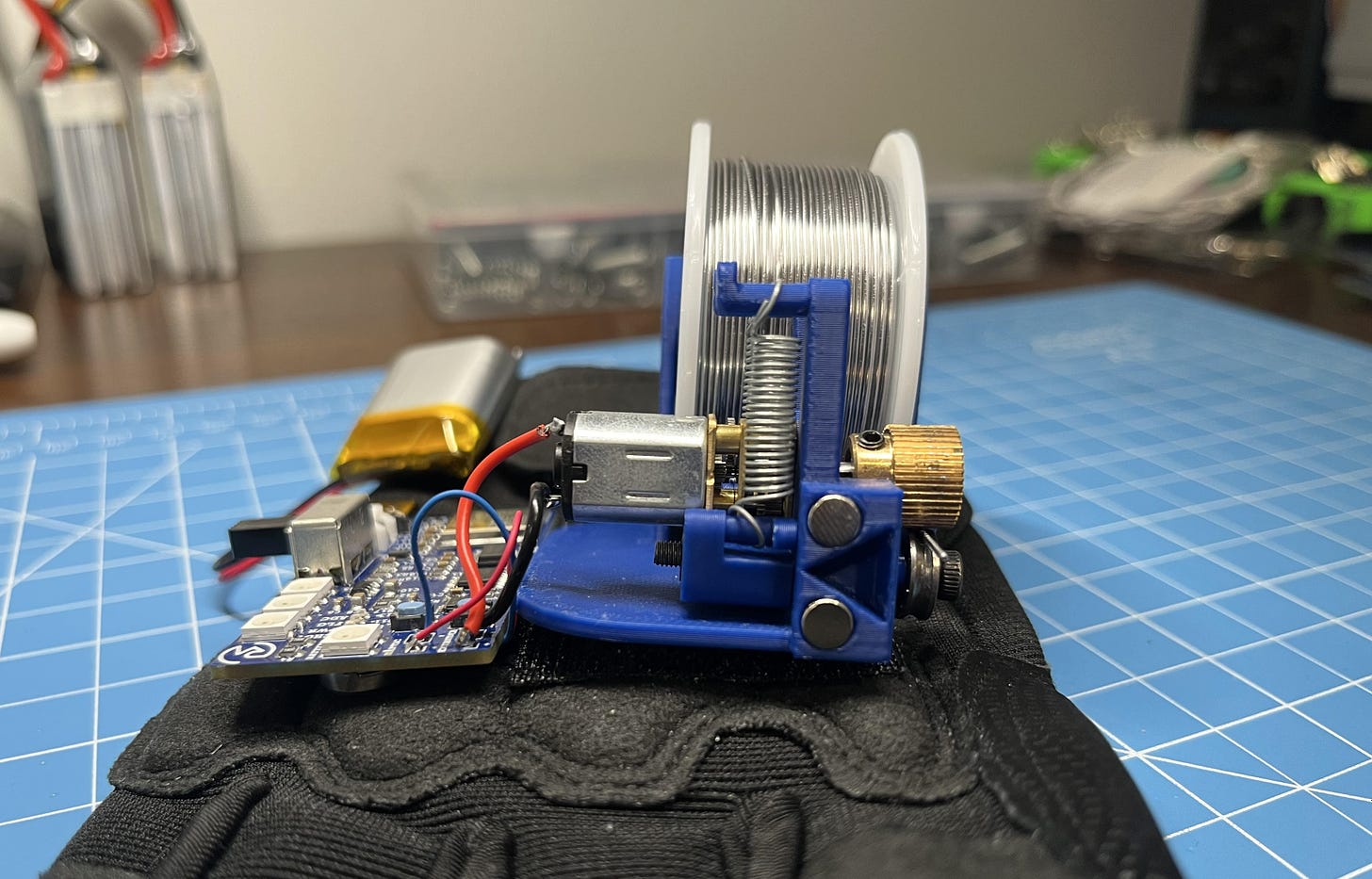
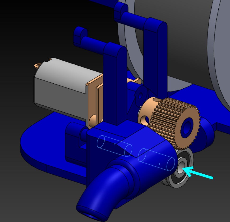
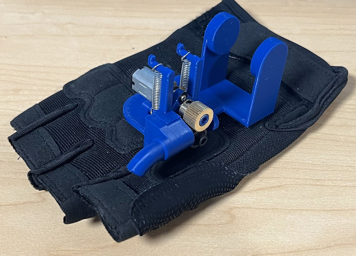
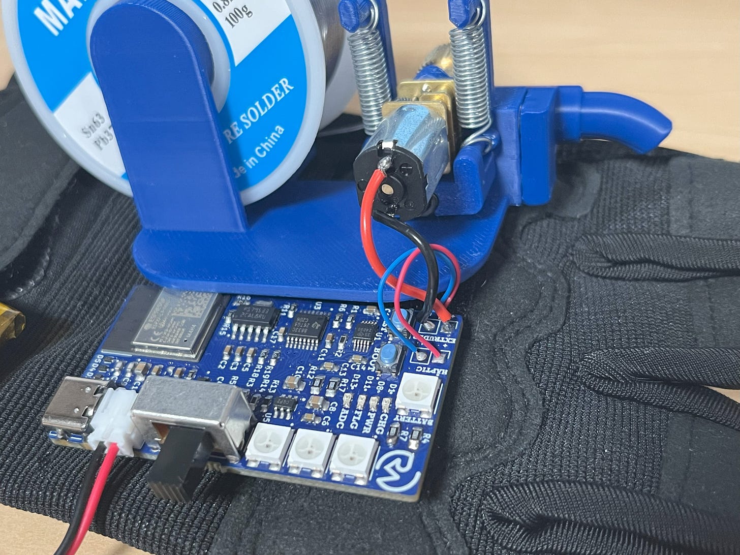
This device works by using a small DC motor with an extrusion gear to move solder over your hand. However, we also need the solder wire to be constantly pressed up against the motor for consistent extrusion. To do this, a neat tensor mechanism is used, which presses a grooved bearing up against the gear with dual extension springs.
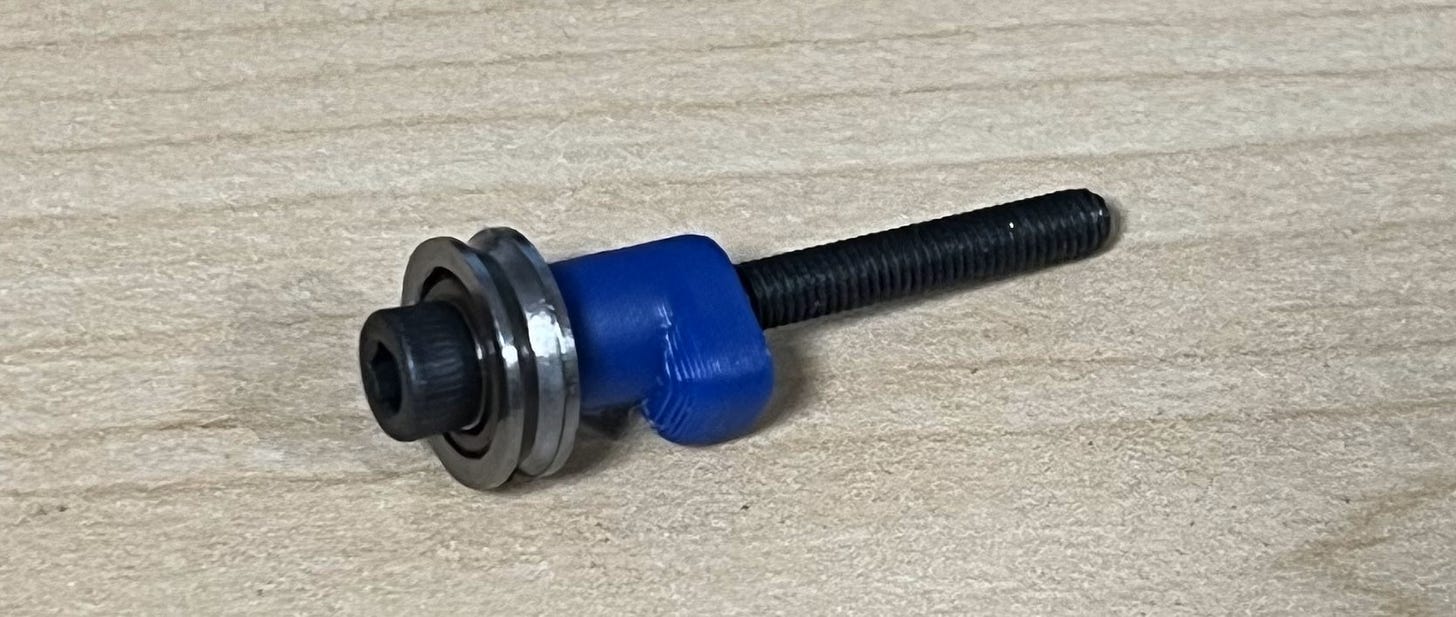
An M3x30mm nut can be passed through the base of the mechanism to connect up the bearing with the extension spring system on the back. The force pulling up from the springs on the back also pulls up on the nut, which presses the bearing against the extruder gear.
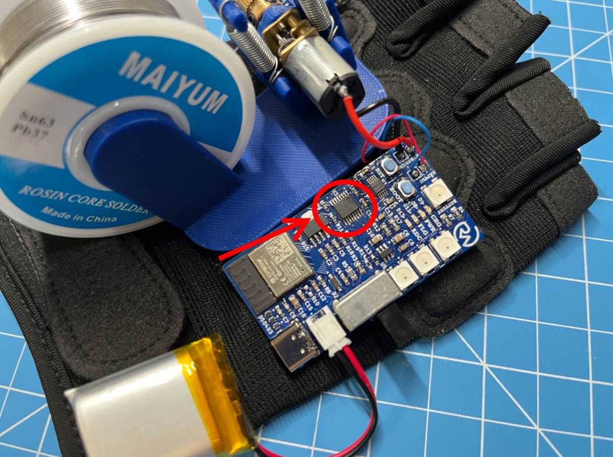
To control the small DC motor with a one-cell LiPo, I’m using a DRV8833 motor driver IC which can handle the motor functions even with the tiny 3.7V we get from the battery. Pretty cool!
To handle wireless communication and other computing tasks, I’m using an ESP32-C3 microcontroller (bottom left of the PCB), which I talked more about in this article.
Understanding the Hardware
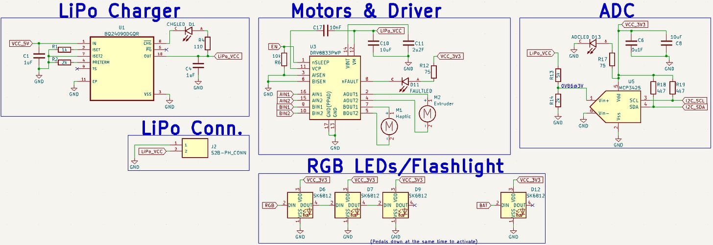
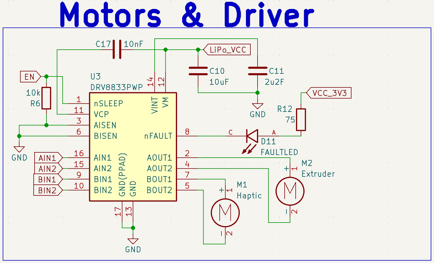
Here is the schematic for our glove circuit board:
*For a higher-quality image, feel free to open these in a new tab.
Let’s break down how it works.
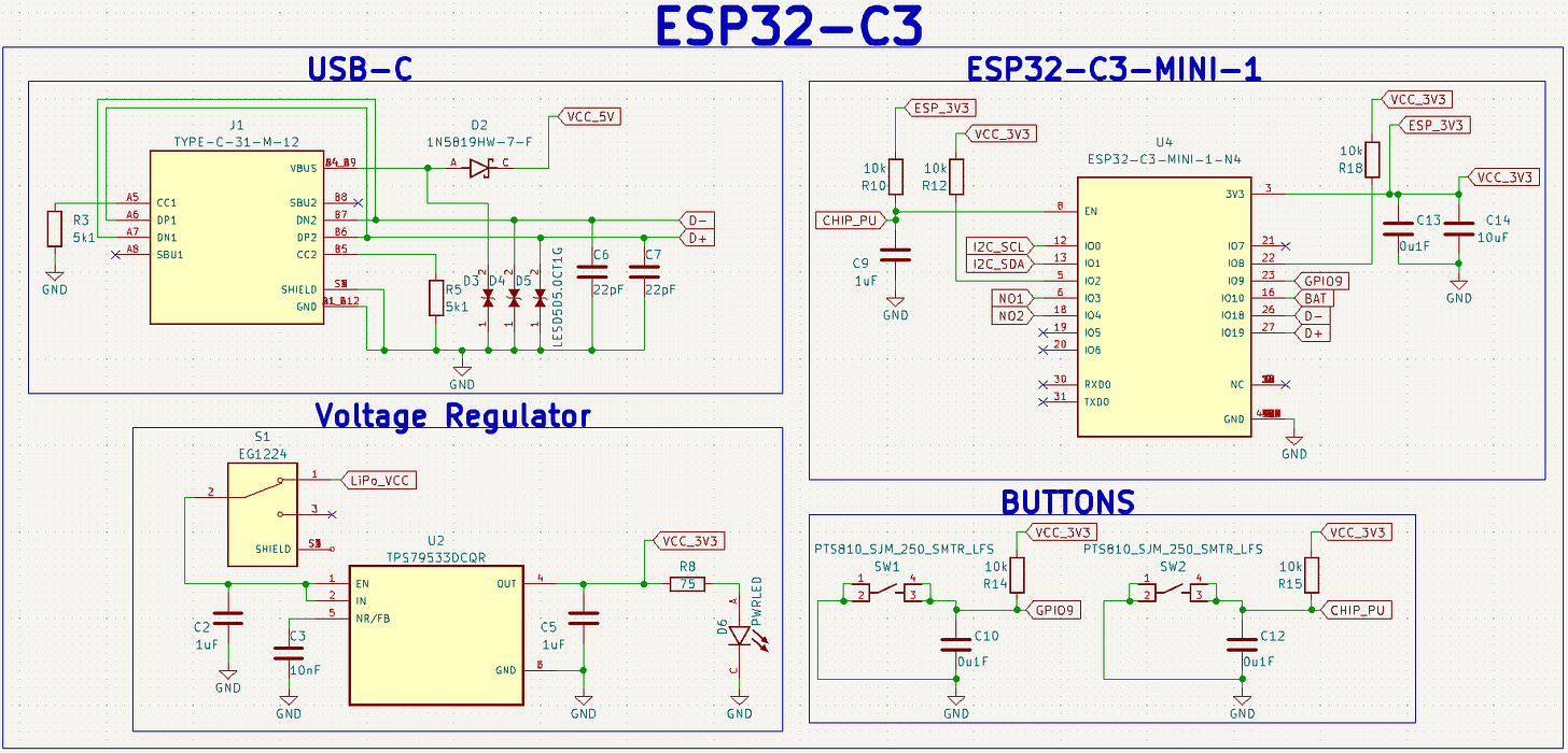
It should be noted that I won’t explain the microcontroller schematic in this article since I covered it in detail here.
First, we connect up our DRV8833 motor driver IC to control the polarity of the voltage and the amount of current allowed to flow into our motors. With this, we can control the direction in which the extrusion motor spins in addition to the speed at which it and the haptic motor move.
The schematic was derived from the datasheet which explains where to place everything. I also added an additional pull-down resistor on the enable (EN) pin to preserve the battery and a fault LED on the nFAULT pin to indicate if there are any problems.
This IC works by using dual H-bridges (to control two motors), each consisting of four MOSFETs (transistors) which can do some neat things depending on which of them are on or off. But that’s for another article. What’s important to know is that depending on four low-power outputs from our microcontroller (AINs and BINs), we can control the direction and speed of each motor (AOUTs and BOUTs) using the duty cycle of a PWM signal.
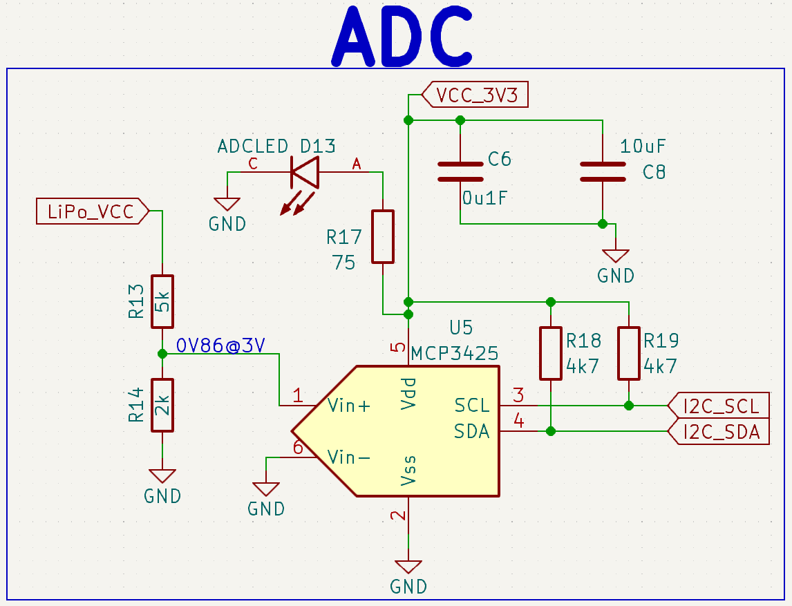
With that done, we can use an MCP3425 16-bit ADC (Analog to Digital Converter) to monitor the voltage of the battery and get a stable reading on how much power is remaining.
The schematic was also derived from the datasheet which explains where to place the capacitors. The resistors R18 and 19 are the pull-up resistors required for I2C communication (which is how it talks to the microcontroller) and the resistors on the left (R13 and 14) are a voltage divider that brings down the battery voltage into a safe range that the IC can measure accurately. (Aka., 0.86V when the battery is at 3V like in the text.)
(If you’re interested, I talked more about ADCs in this project.)
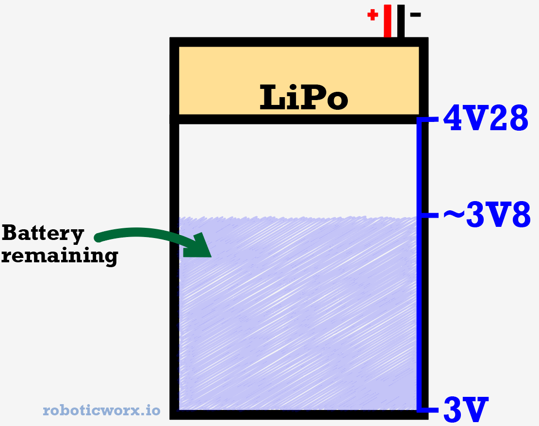
This IC (Integrated Circuit) is useful because batteries have the property of decreasing in voltage proportionally to how much life they have left in them. We can use this 16-bit ADC to read that voltage accurately and get a read on how much life is remaining. Even though our microcontroller has a built-in ADC, it is only 12 bits (0-4095) which isn’t quite accurate enough to get a stable reading without fluctuations (16-bit goes from 0-65535)!
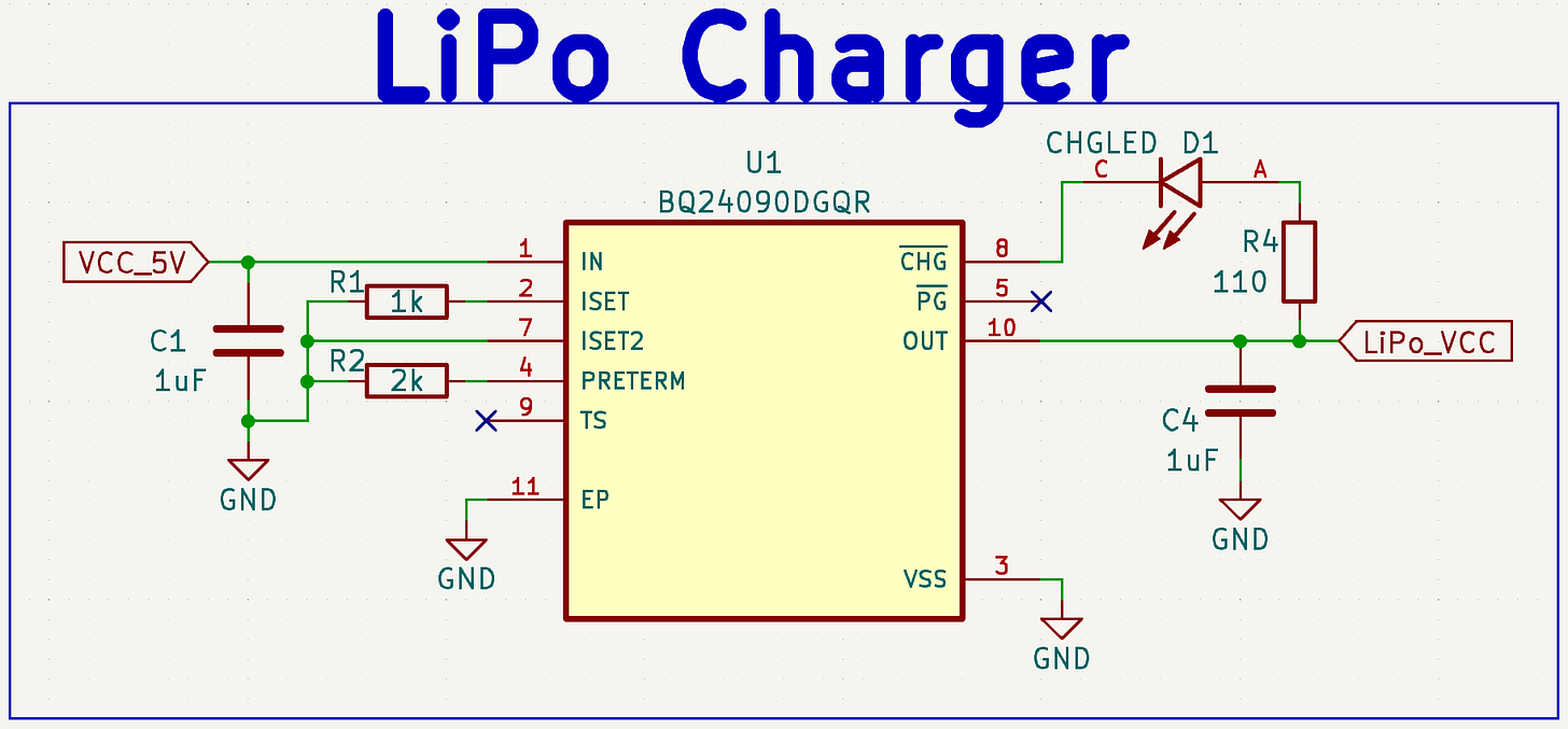
For handling battery charging, I’m using a BQ24090DGQR one-cell LiPo charger IC. This basically just shoves 4.2V into the battery whenever I plug in the USB-C, in addition to monitoring the battery itself so that it can stop charging whenever the battery gets close to fully charged.
Same deal as the other two, the datasheet for this IC can be found here. The two resistors (R1 and R2) in this case, are used as programming resistors, to determine how fast or slow the battery should be charged and when the IC should decide to stop the charging.
The cool lights I’m using are SK6812 RGB LEDs, which basically just change color based on the PWM signal they receive, but more about that in the programming section.
The “RGB” and “BAT” labels are PWM signals. One for the main soldering light LEDs, and one for the battery indicator LED.
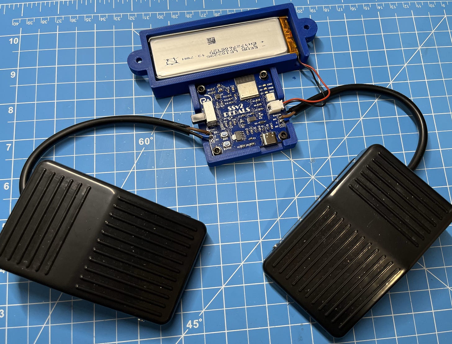
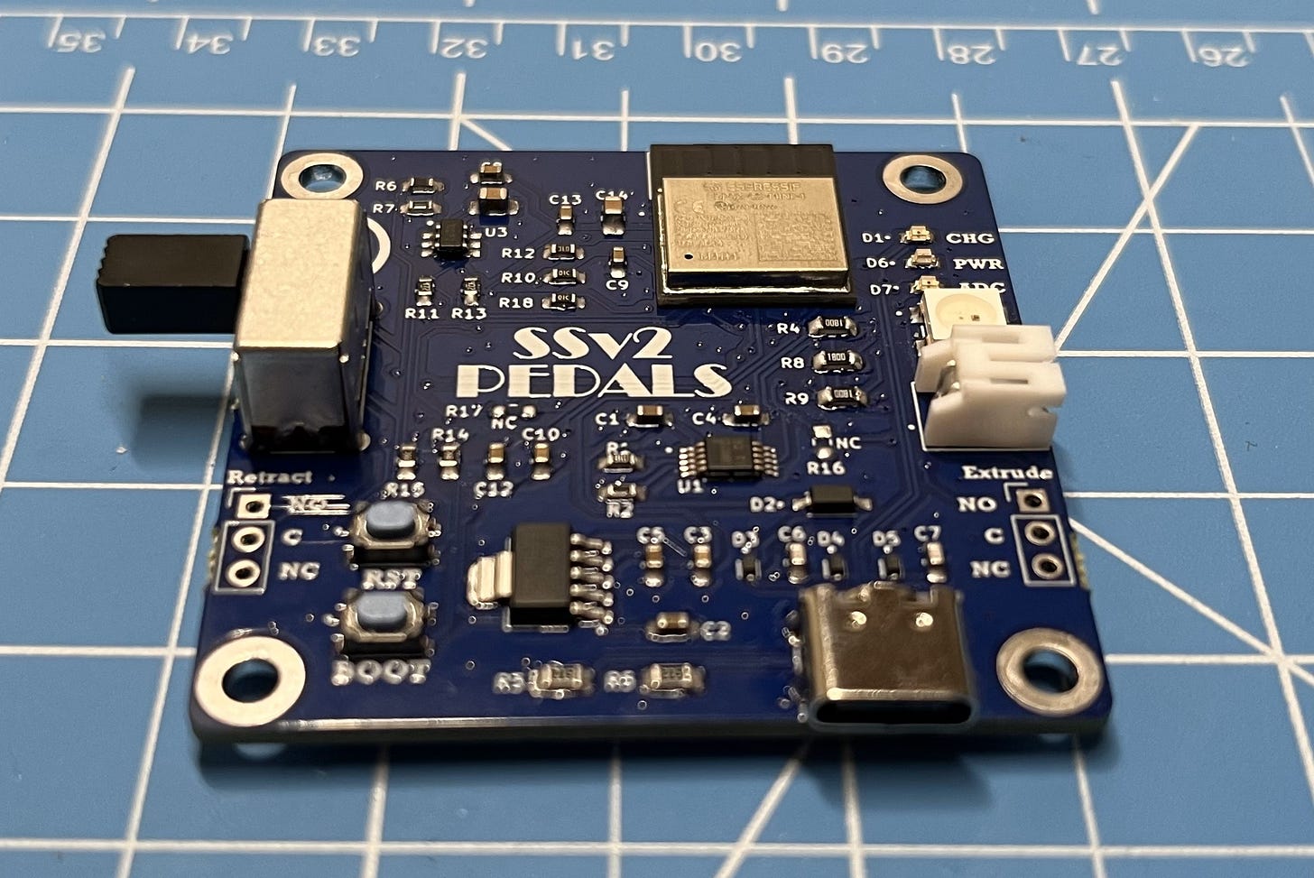
For the pedal PCB, I’m really just using the same setup as the glove PCB except without the motor driver IC/soldering lights, and with some added pin headers to connect up the two pedals.
For a higher-quality image, feel free to open these in a new tab.
The principle behind the pedals is pretty basic, three wires come out of each, a common (C), normally closed (NC), and normally open (NO) wire. All that happens when you press on the pedal is that it closes the NO connection, and “opens” the NC. This means that if we pass a small voltage to the common wire, that voltage will show up on the NO wire when the pedal is pressed. Since we want a high signal, this is perfect. There is no need for the NC wire in this case, which is basically just the inverse (if you want a low signal when pressed). This signal is then sent to the glove through the ESP-NOW protocol for each pedal.
Building the Boards
Now, let’s dive into the actual PCB (Printed Circuit Board)!
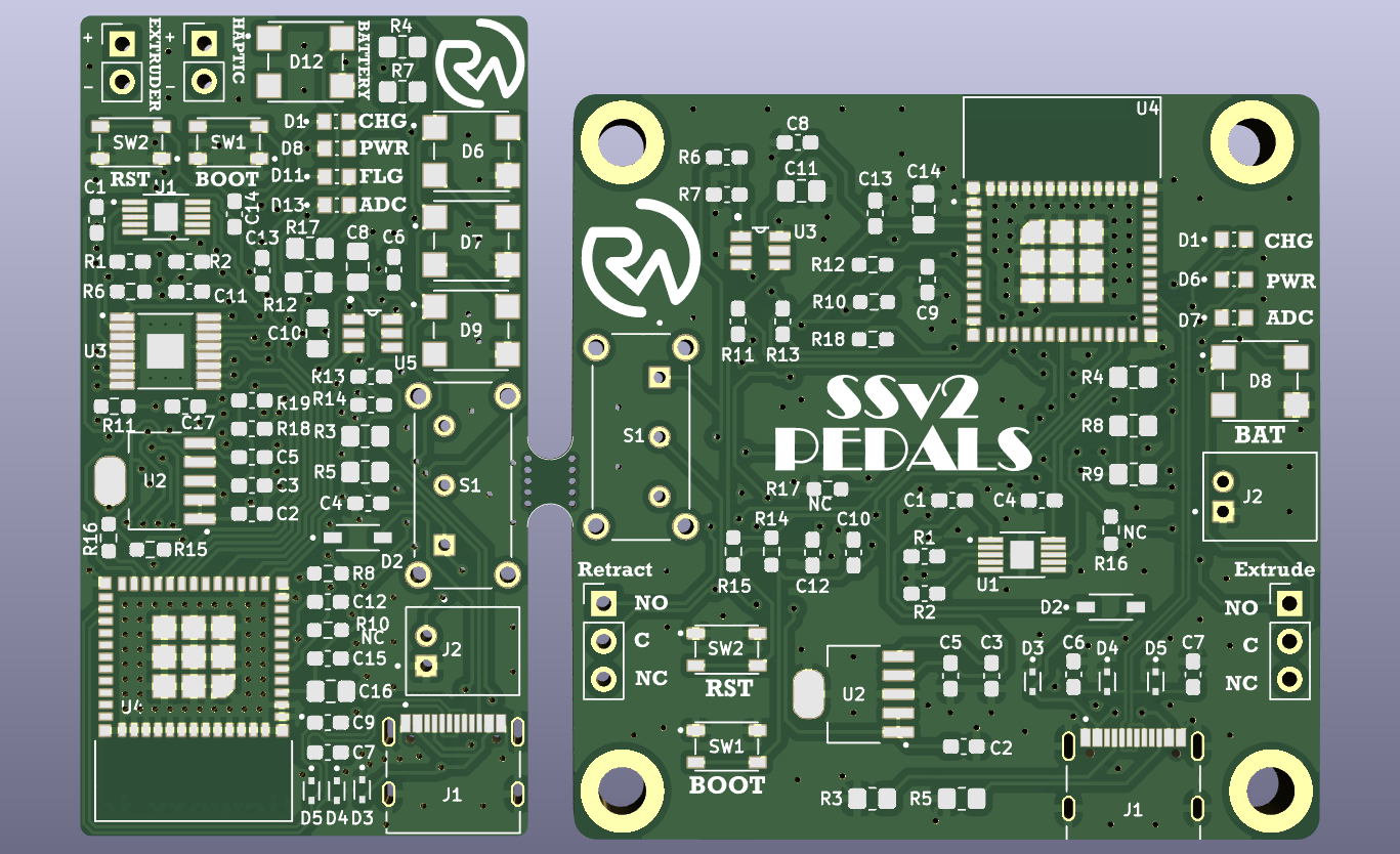
Here is our final layout:
The glove PCB is on the left, and the pedal PCB is on the right. Once you’re done building the board, you can break the connection between them.
What’s really awesome about the glove PCB, is not even how much it’s able to integrate together but how compact it can do it in! The PCB is only 55x30mm! Certainly one of my toughest, but favorite designs so far.
- The right-handed Gerber/fabrication file for the board can be found here.
- The left-handed Gerber/fabrication file for the board can be found here.
- Editable KiCad PCB files are available here to paid subscribers. Want to become a paid subscriber? It’s only $5 and I would really appreciate your support!
- The part list for the glove PCB can be found here.
- The part list for the pedal PCB can be found here. You will need to download this one (click “download raw file”).
- As always, I know that it can seem like a pain to have to order parts but it’s really not so bad as almost all the parts you order from one project get reused. Think about how much you’ll learn with some hands-on experience!
If you’re interested in learning more about PCB layouts and routing, check out Robert Feranec and Phil’s Lab on YouTube. They’re great designers and I’ve learned a lot from them.
Of course, to have this board made we will need to go through a PCB manufacturer. As always, PCBWay was my go-to!
Their PCB quality is always super amazing, and they even have CNC and 3D printing services that you could use if you’re looking to build this project but don’t own a printer yourself. Plus, they have a neat KiCad plug-in so I can check out without even leaving my design software.
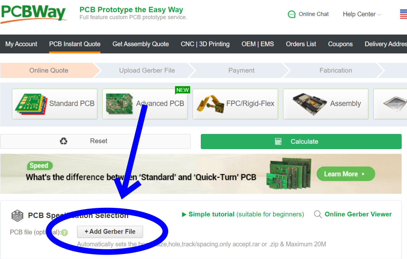
However, you can always just order through their website by going to PCBWay.com, clicking on quick-order PCB, and uploading the Gerber/Fab file (right or left) for the board. Or alternatively, just go here which I have saved in my favorites bar. I recommend clicking the stencil option at checkout to save some headaches!
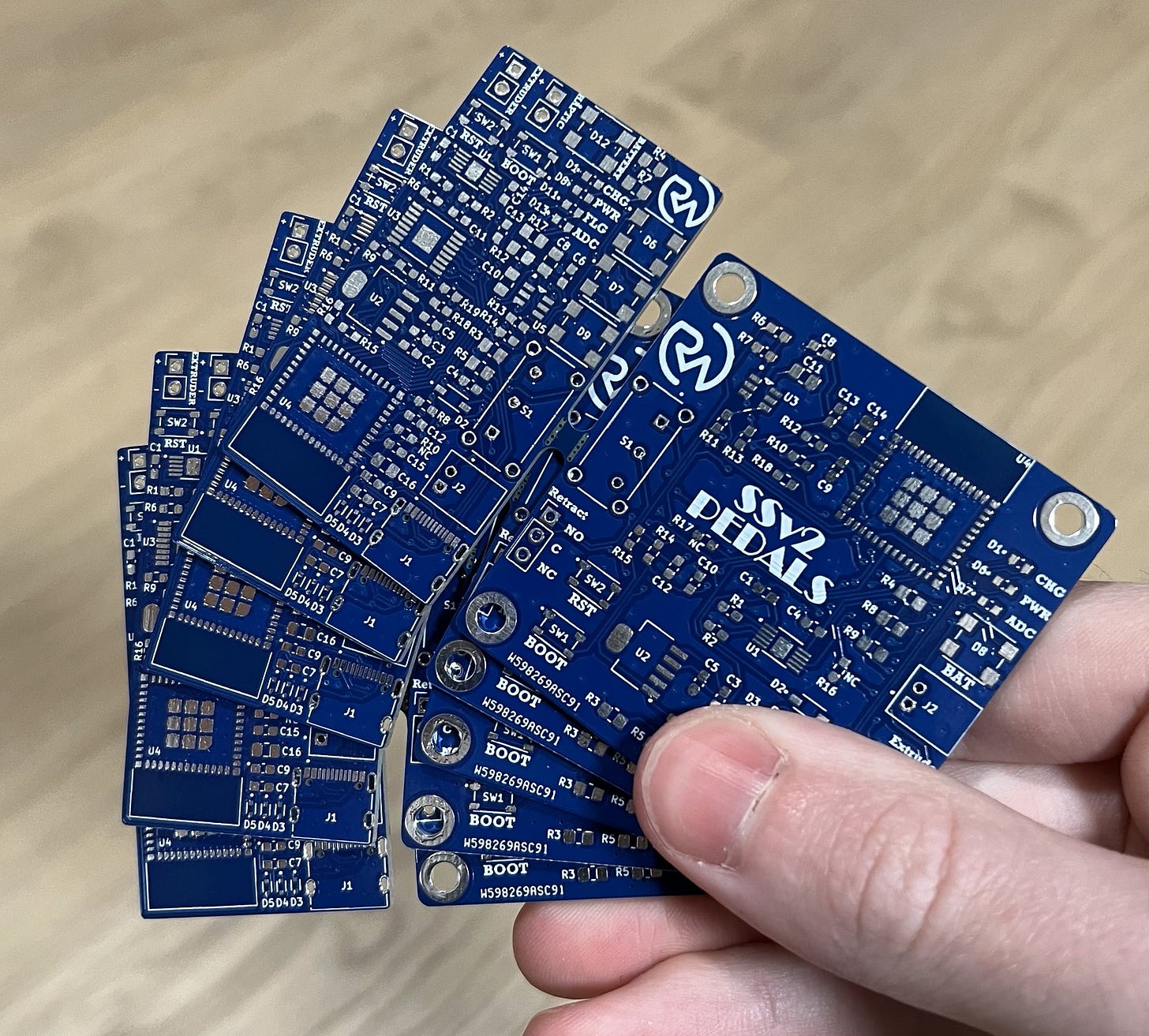
I chose mine to be blue to match the 3D print. But, if you decide to build your own, you can pick yours to be any color you want! PCBWay has a huge variety to choose from.
The PCBs looked perfect once they arrived a few short days later!
Now we can assemble the board!
- The reference/placement sheet for the glove PCBcan be found here. This is the same for both the right and left-handed PCBs.
- The reference/placement sheet for the pedal PCBcan be found here.
NOTE:The DRV8833 motor driver IC for the left-handed version of the PCB is placed upside down! This is marked on the board, but I wanted to say it again here in case there’s confusion. It was designed like this to allow more space for the traces to connect with the microcontroller. This only applies to the left-handed PCB.
Here’s a short video to walk you through the board assembly process:
Step 3:
Perfecto!
*Pedal PCB.
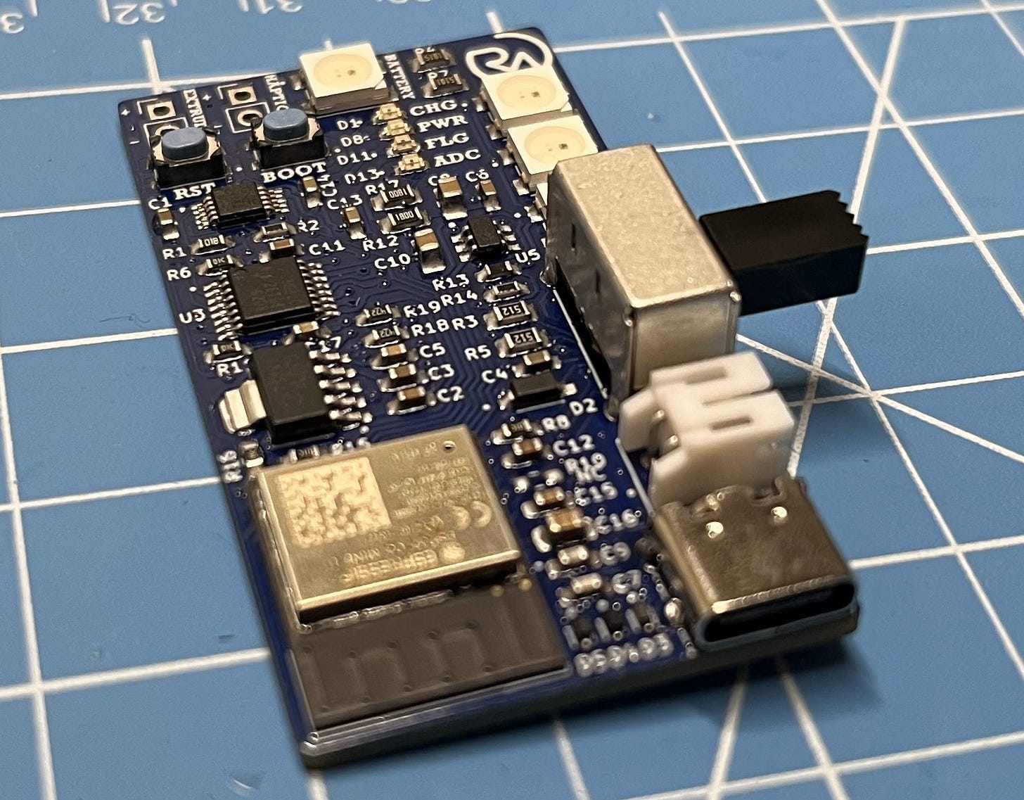
*Right-handed PCB.
I also made the left-handed PCB to ensure it worked the same as the right-handed one - all good! It is below for reference.
*Left-handed PCB.
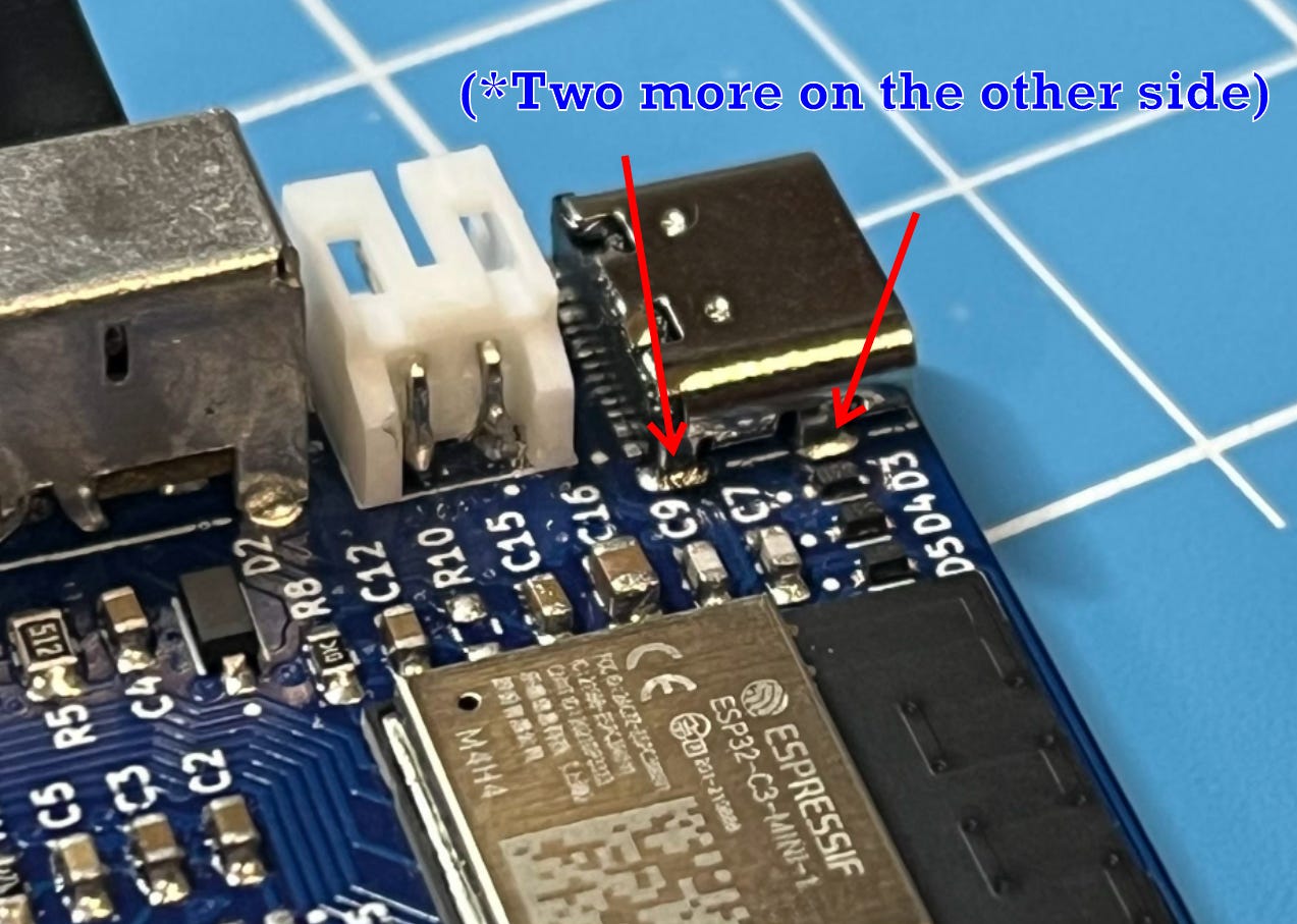
Important note: Be sure to also solder the four USB-C pins to the board after hand soldering the switch and battery connector! If you don’t do this, the port will likely break off as soon as you plug it into something.
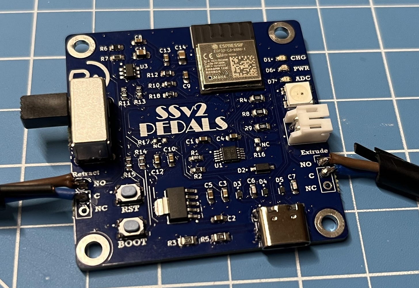
You can also go ahead and solder on the foot pedals to the pedal PCB. If you bought the same pedals as I did, just copy the colors. If not, match your foot pedal to the NO, NC, and C pins labeled on the PCB which I explain in the schematic section.
*Blue wire to “C”, brown wire to “NO”. No need for the black wire.
Building a Version 3
No doubt, this puppy is super awesome. I’ve never had an easier time soldering! But, no device is perfect.
I’ve already gotten some super great feedback through comments on my socials, which I would love to integrate into a Solder Sustainer v3. Including:
- A fume extractor that’s built into the tube where the solder comes out.
- More lightweight design. Yes, I think I can make it even smaller!
- Extrusion system that doesn’t have to be close to the iron. (Basically a desk-based system that you don’t have to hold.) This is challenging because the solder wire clumps up if it’s being extruded from too far away, but I’d love to try and solve it! If you’d like to see how I do, be sure to subscribe! :)
I’d love to continue hearing your feedback, so let me know what you think in the comments below.
Assembly
The STL 3D printer files can be found here for free on my Thingiverse! (Left-handed CAD is also available!)
If you’re interested in obtaining the logo-less STL files in addition to the editable STEP files, please consider becoming a paid subscriber! I don’t use ads, so I rely on your support! Plus, it’s only $5 and you will receive the following benefits. Already a paid subscriber? Access your materials here!
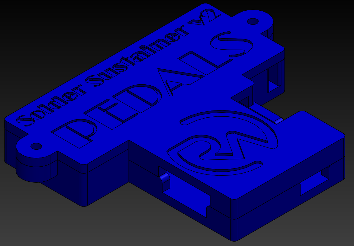
*Pedal PCB casing.
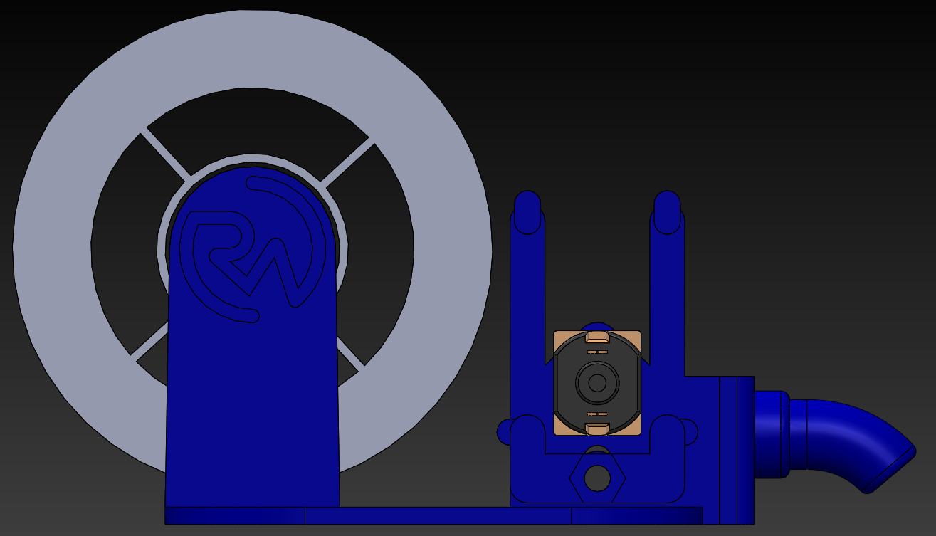
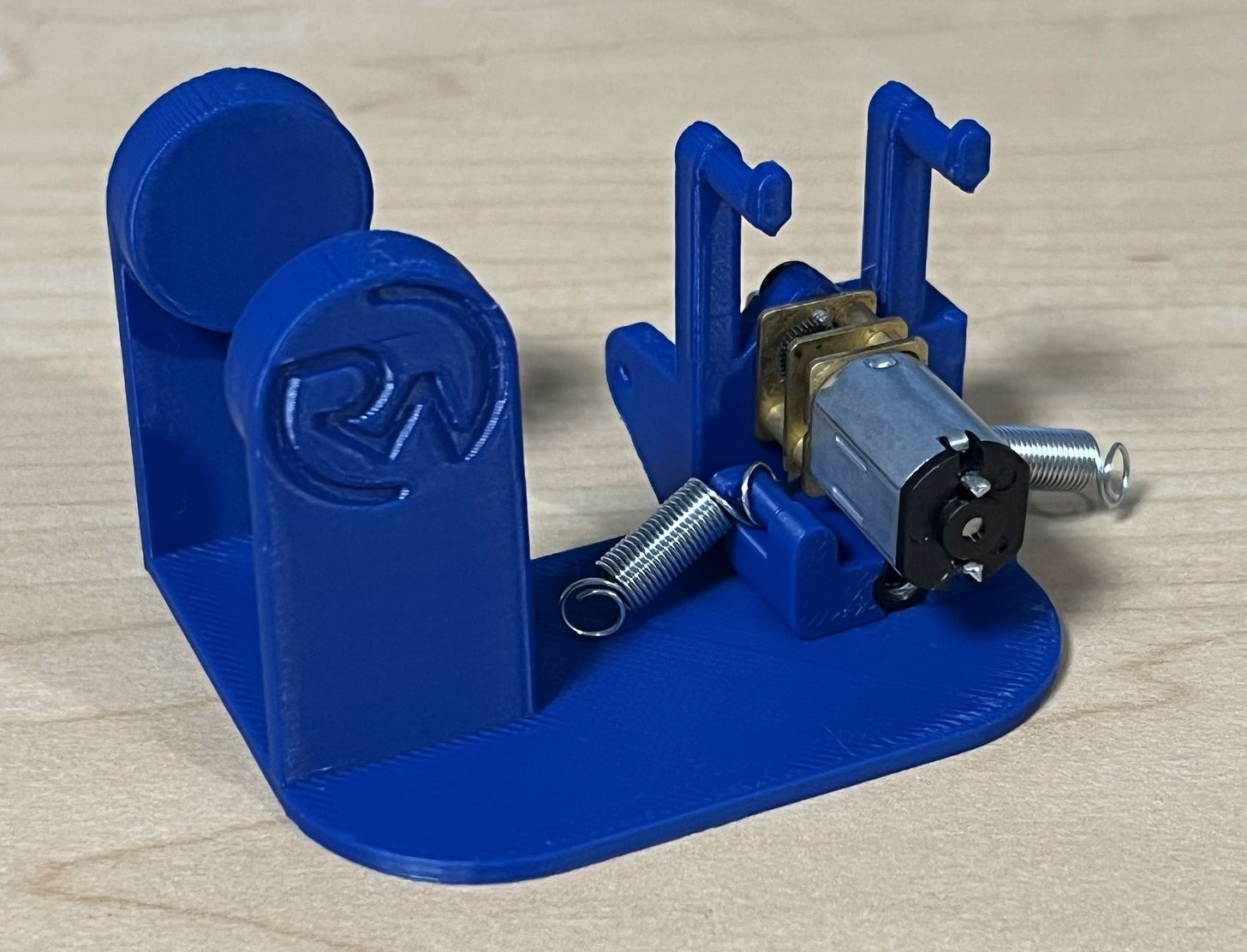
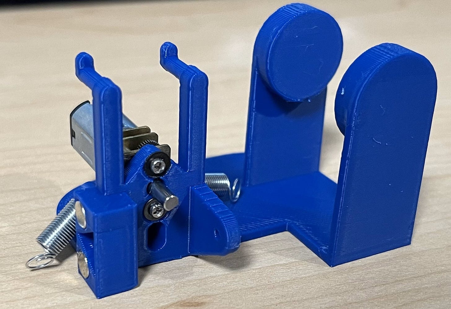
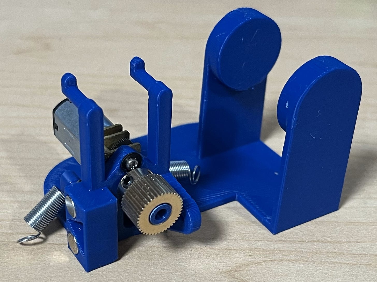
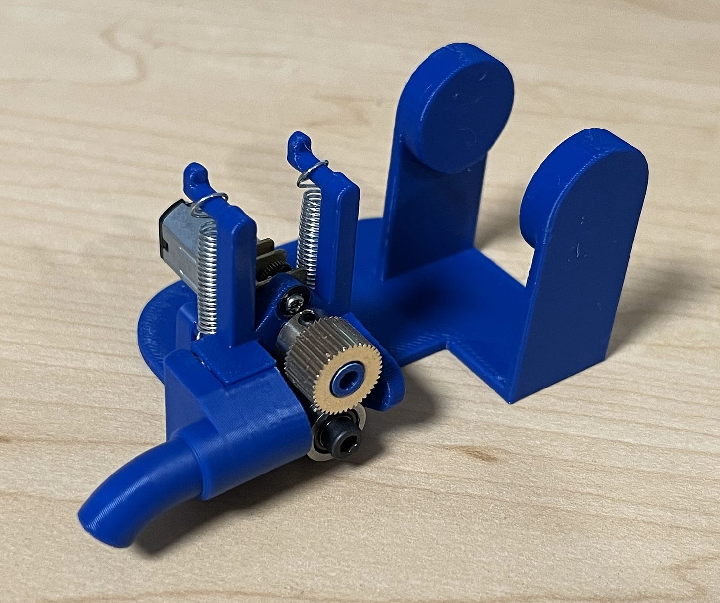
*Extruder mechanism.
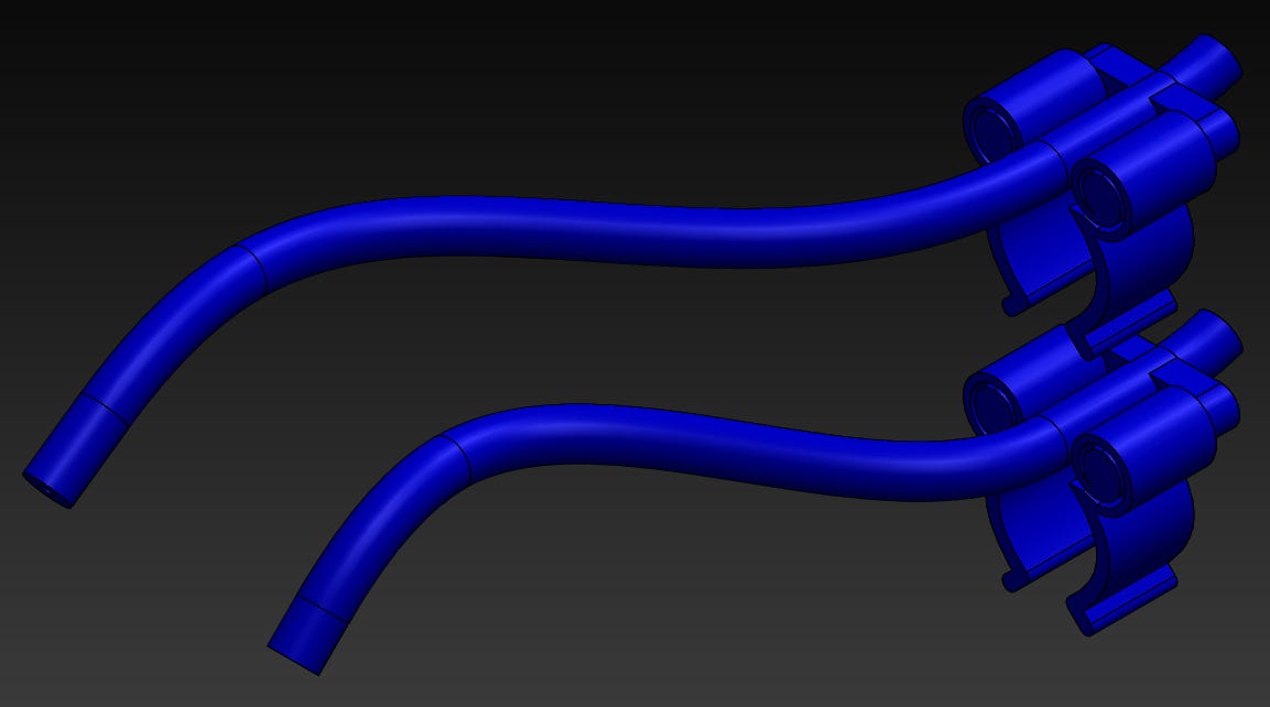
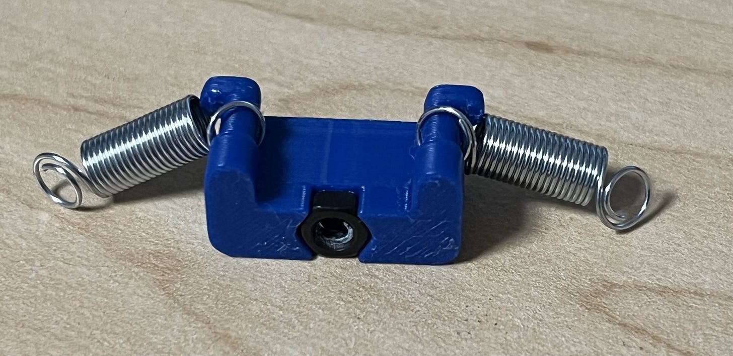
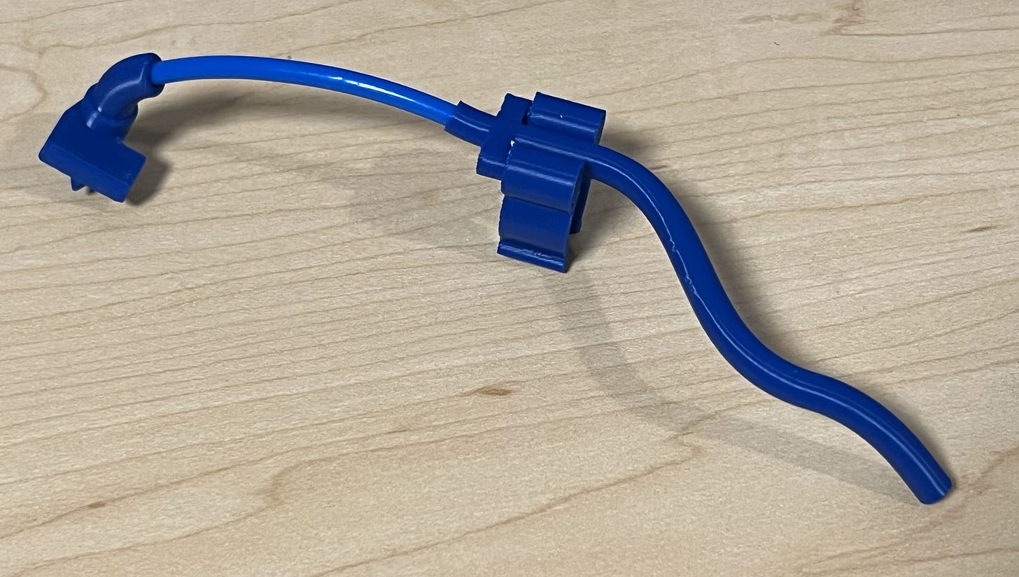
*Solder guides - two sizes for generic and mini soldering irons. The finger grip looks funny because it uses printed coil springs to fit any sized finger.
Let’s get started! First, I’ll go through the assembly of the extruder mechanism.
Want to skip over the assembly section? Click here to save some scrolling!
Go ahead and grab the base housing piece and insert two Neodymium magnets. You will need to put a dab of super glue in the housing before you push the magnets inside to secure them to the print.
Next, slide on two 13/64”x13/16” extension springs using the base tensor piece and pop in an M3 nut.
When that’s done, grab your micro DC motor and slide the shaft into its spot in the base housing. You’ll also want to place the piece you just made under it so that the motor is resting on top of the tensor.
Next, secure the motor in place using two 1.6x6mm screws and some M2 washers.
After that, push the extruder gear spacer part inside the extruder gear and slide it onto the motor shaft. Be sure to line up one of the M2 tensing bolts in the extruder gear with the flat side of the shaft for maximum grip.
Then, grab an M3x30mm bolt, your grooved bearing, and the bolt spacer piece and make a sandwich.
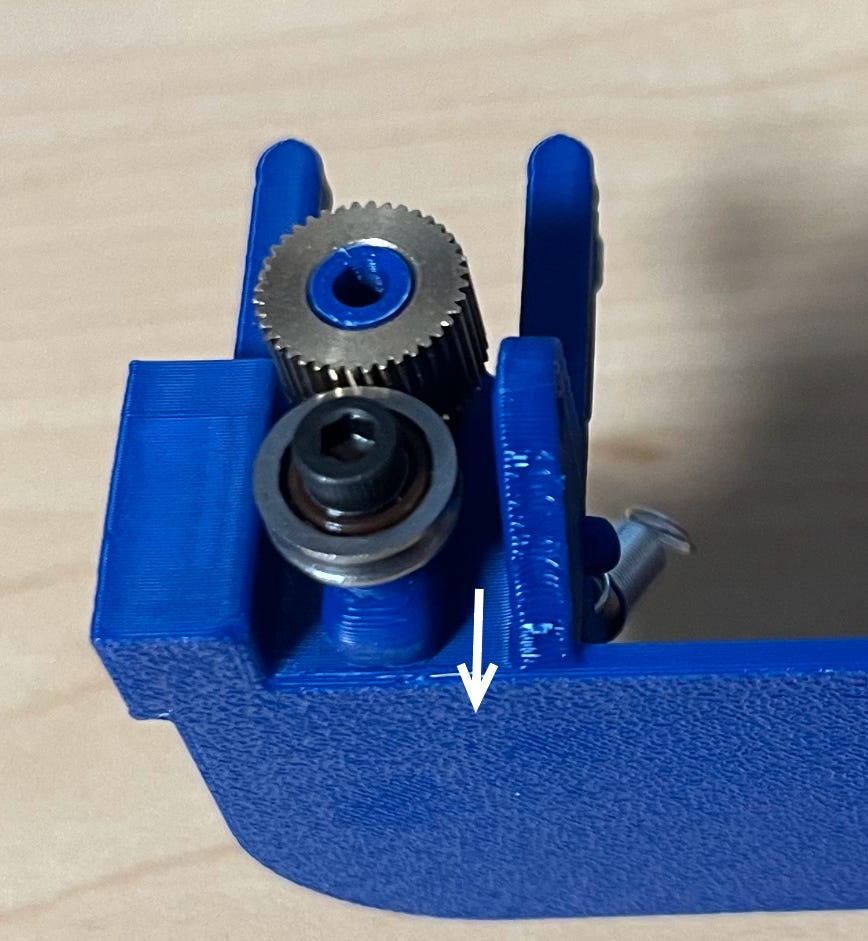
With that, screw it in all the way through so that it comes out through the nut on the back of the tensor piece. Be sure that the flat piece of the spacer is pointing down so that the piece can stay straight even when the springs start pulling on it.
Make sure it’s secure, but not too tight! You want it to be able to slide up and down.
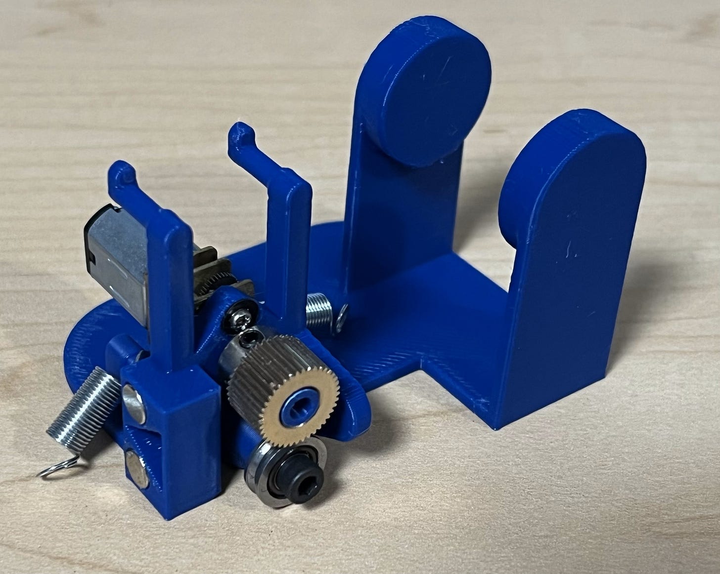
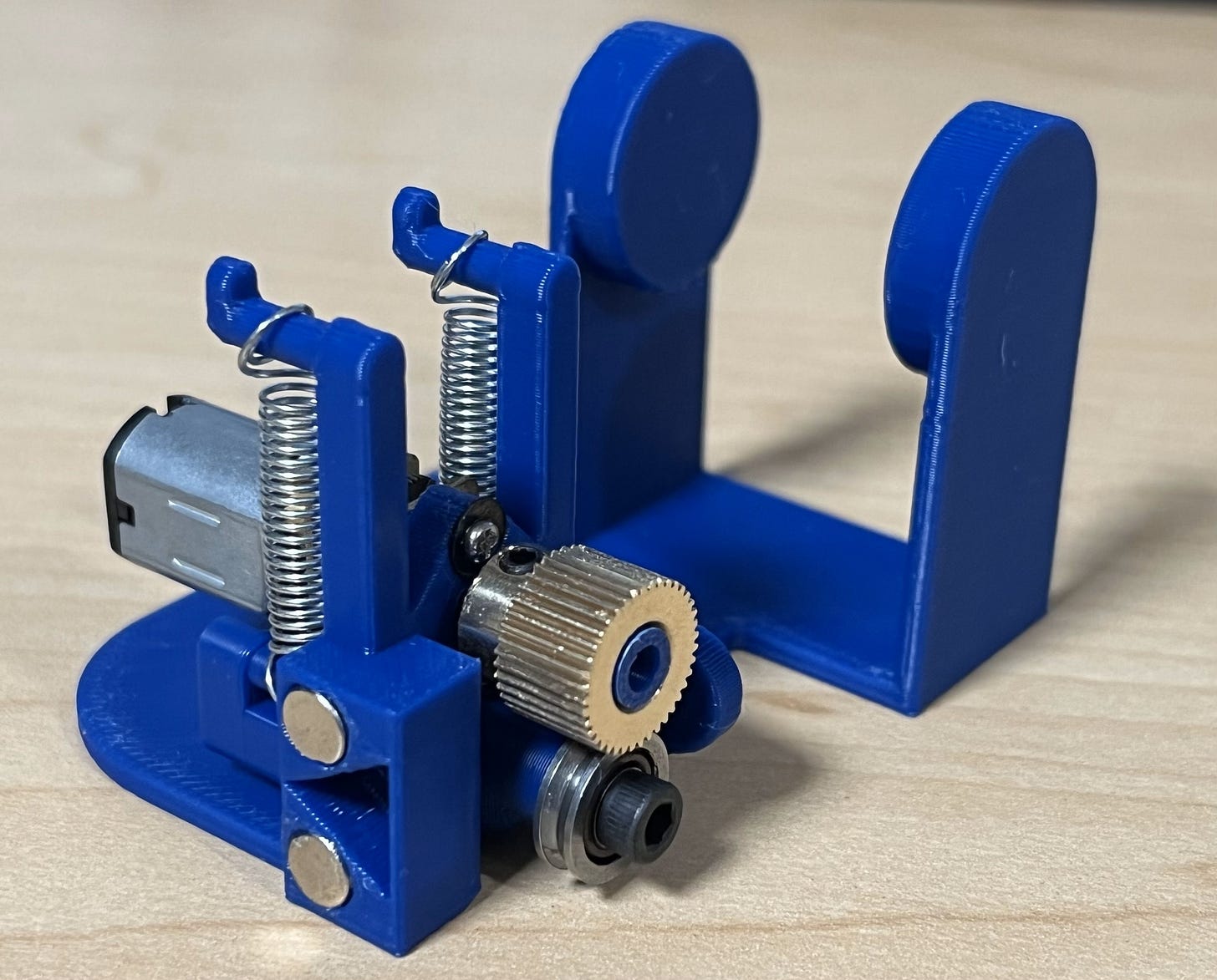
Then, pull the extension springs up and over the hooks. Some tweezers may make this a bit easier.
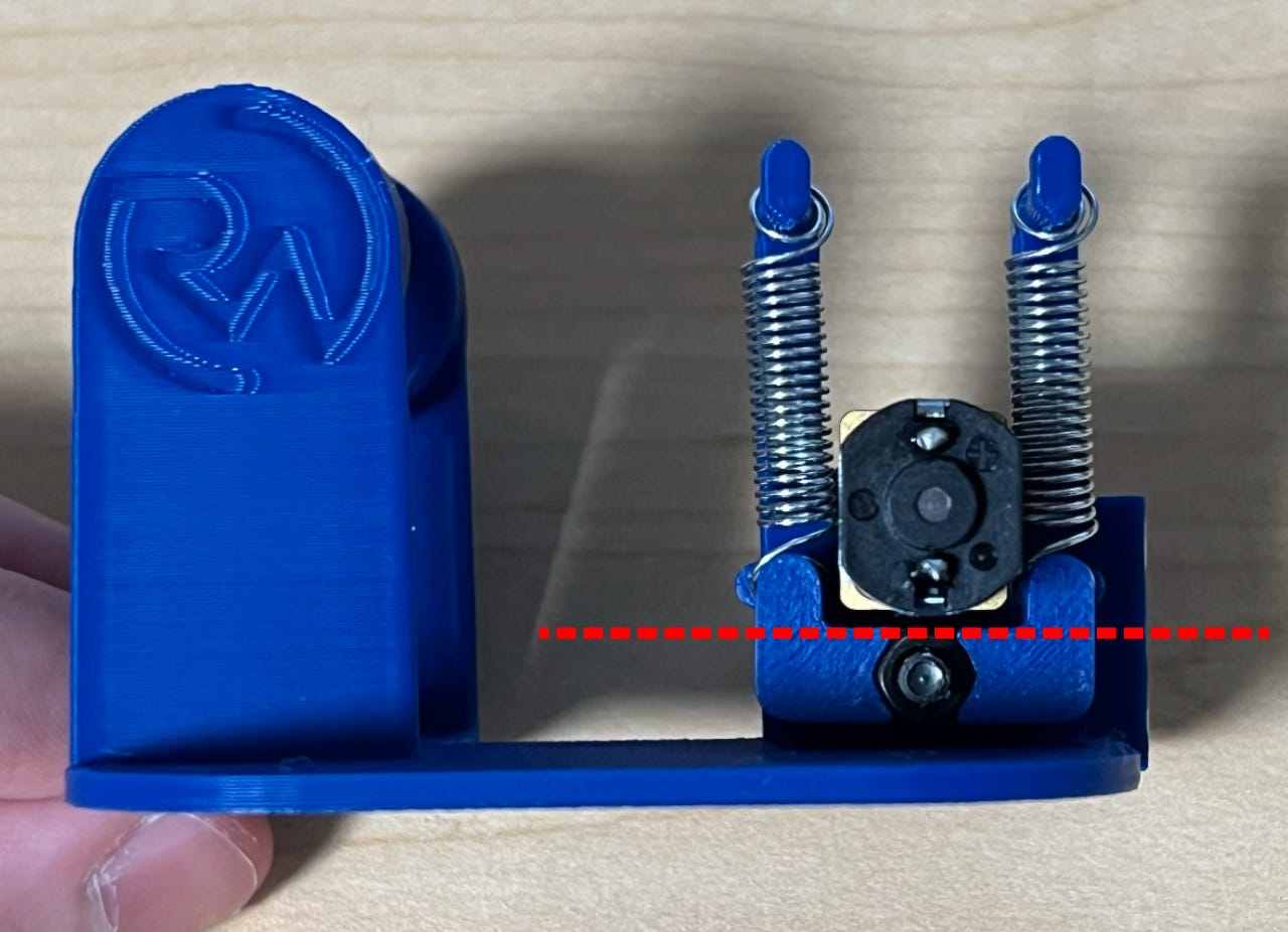
Something else important to note is that the tensor piece must stay parallel to the bottom of the motor. If it gets too crooked, the bearing may not be able to press on the solder wire enough, resulting in slippage.
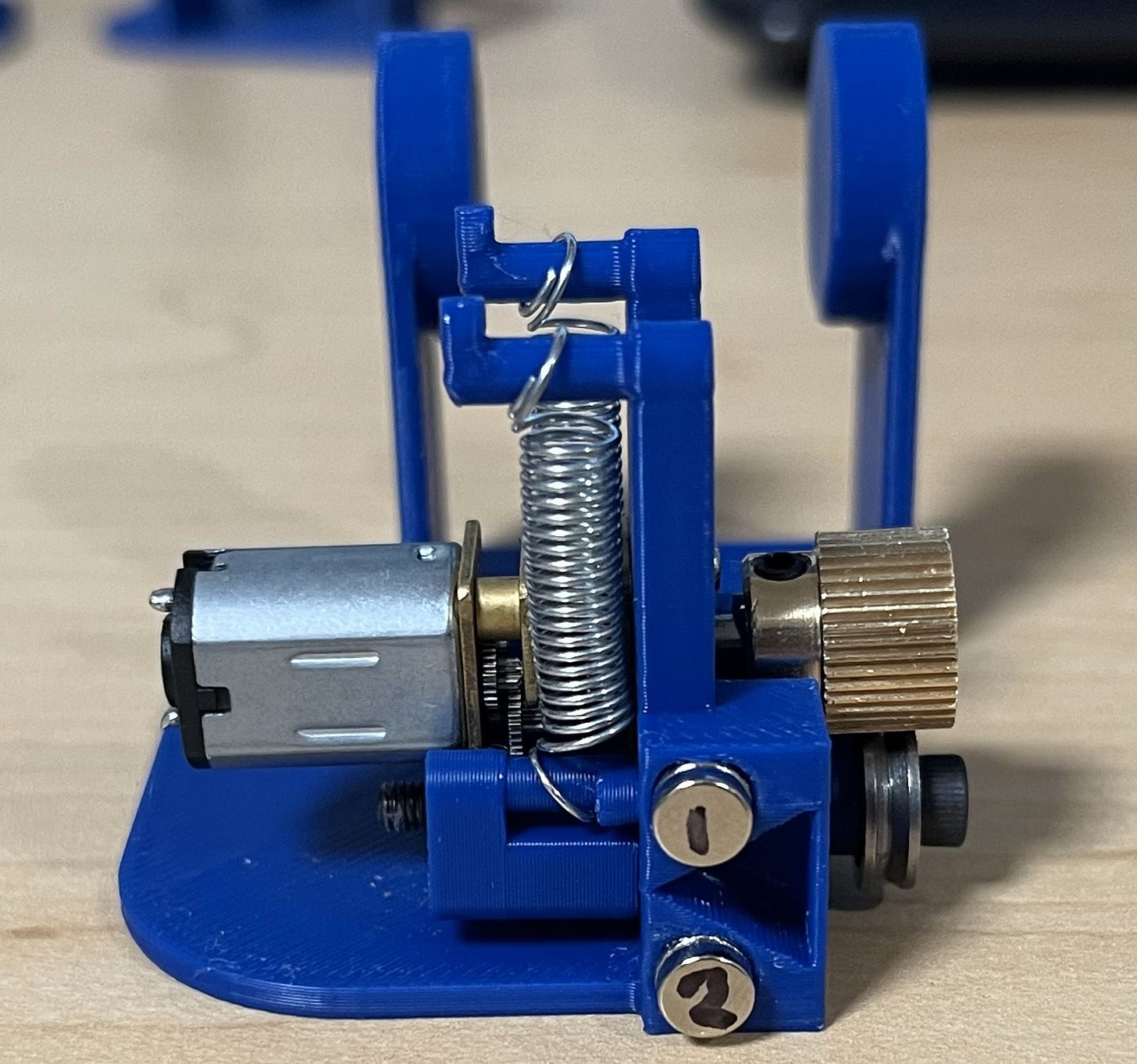
After that, grab two more magnets and pop them onto the ones you already mounted. Then, mark the top one as “1” and the bottom one as “2”. This will help later.
Once they’re marked, grab the solder guide piece and pop in the magnets accordingly. Make sure to use some super glue! The magnet marked “1” should be on the side closest to where the solder wire runs, with both magnets facing inward so you can’t see what you wrote on them.
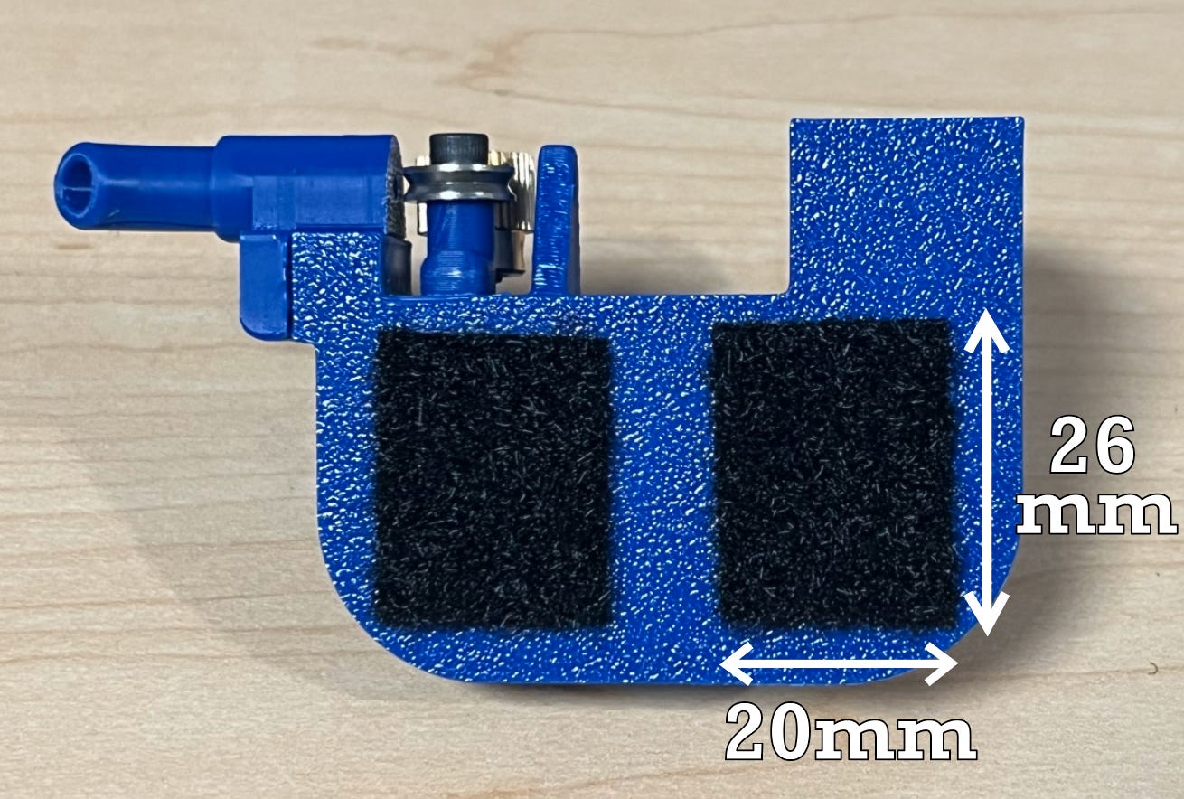
Next, bust out the velcro strips. I’d recommend cleaning the bottom a bit before putting them on for the best adhesion.
The dimensions are the same for both.
It should be noted that the company I bought the Velcro from recommends letting the strips sit for the first day to get the maximum stickiness. Do what you will with that.
You can go ahead and stick the corresponding velcro on the glove too, including one for the battery.
*The two extruder pieces are the same dimensions.
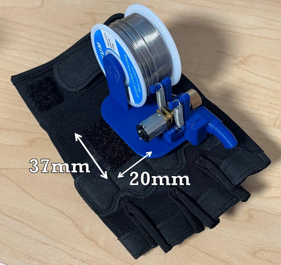
Then, pop on your extruder assembly! Do your best to line the velcro up such that the assembly is as far right as possible (fingers out view) while still fully touching the glove velcro.
You can slide the roll on next if you’d like.
Looking good!
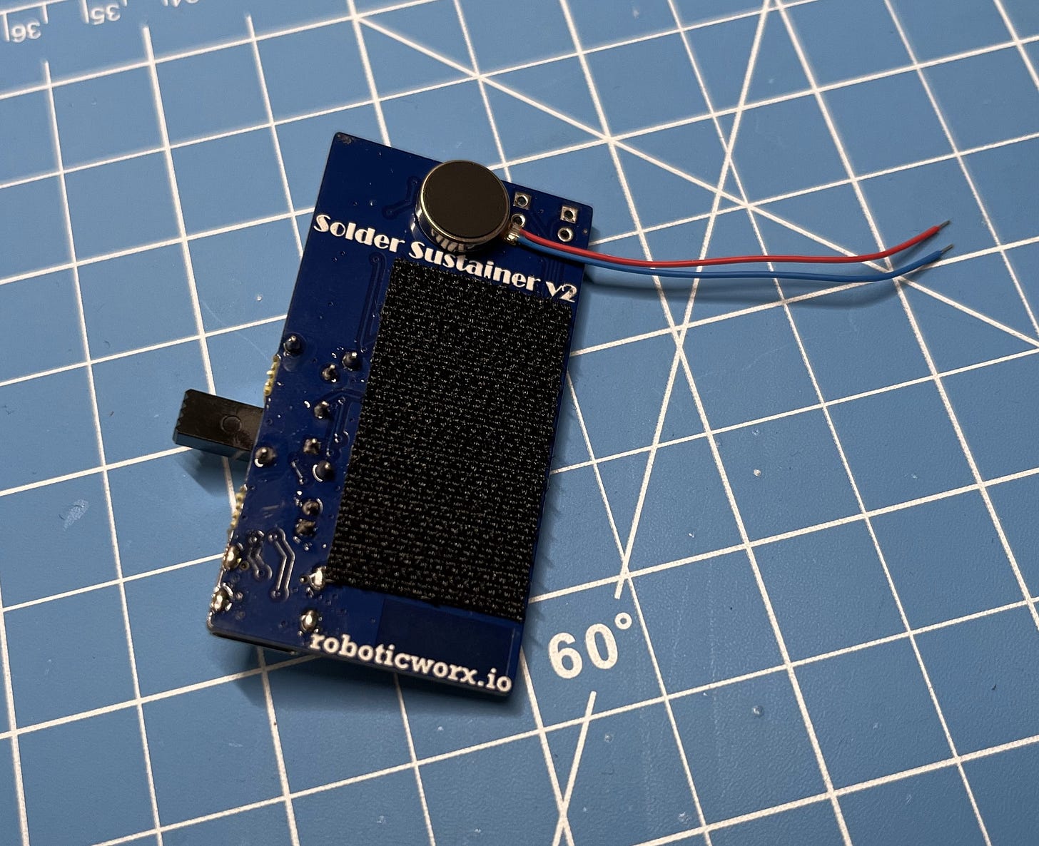
After that, grab the glove PCB and stick some Velcro on that too. I recommend cleaning the surface of the PCB as well for the best adhesion. If you haven’t yet stuck on your haptic motor, you can also do that now.
*The Velcro is 20mm wide.
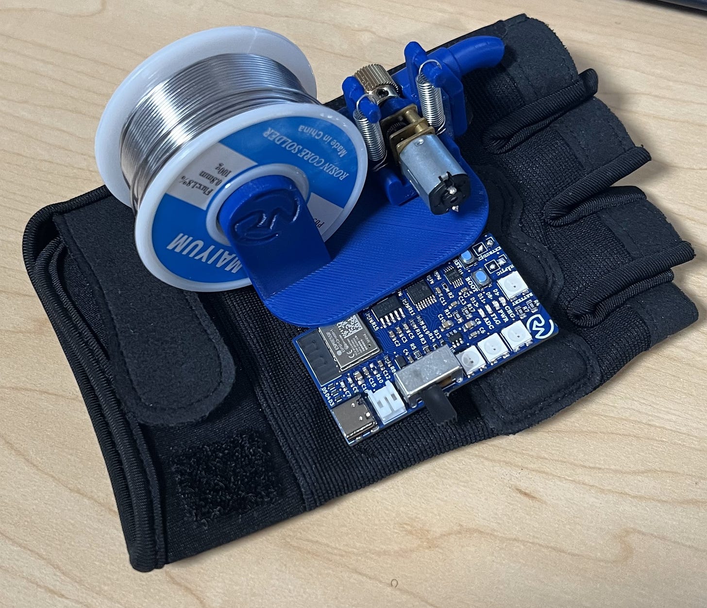
Next, place the corresponding Velcro on the glove. You will want this to be as close to the other Velcro pieces as possible! Ideally, it should be touching the other Velcro pieces underneath the extruder assembly.
Then, you can mount the PCB. This too should be going underneath the extruder assembly a little. If it doesn’t, it’ll probably feel too far away from you whenever you are actually wearing the glove.
Let’s put Velcro on the battery next.
Now, we can solder up the connections, stick on the battery, and insert the connector!
Awesome!
To handle the rest of the solder tube/guide is pretty easy. First, just detach the magnetic solder guide already on the assembly and push the Bowden tubing inside. It should fit snugly. Then do the same for the adjustable solder tube piece.
I recommend starting with a rather long length of Bowden tubing and then shortening it once you have the glove on. The ideal length should be so that the magnetic solder guide piece is flush with the extruder assembly while your finger is flexed slightly. This may take a few attempts, so start long and shorten it slightly every time until it’s right for you.
That’s all for the glove assembly!
Don’t worry, the pedal is super easy.
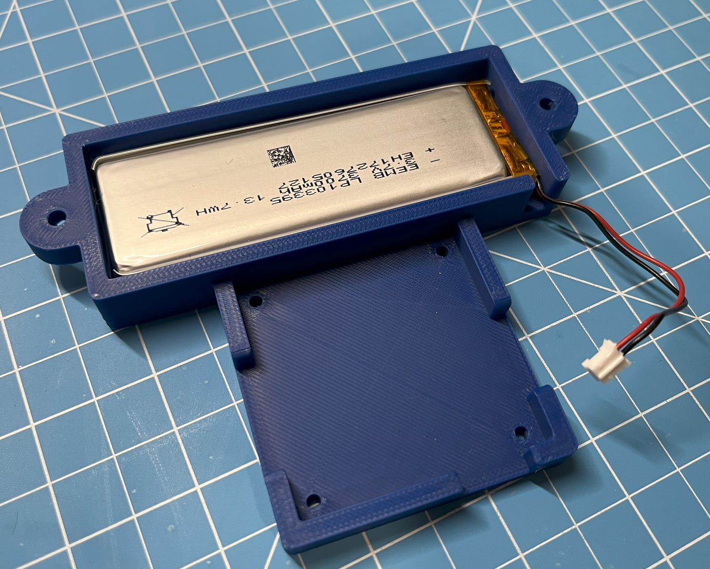
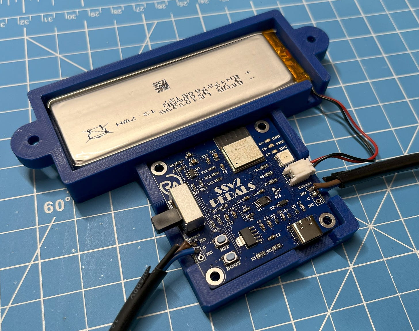
First, grab the bottom casing piece and pop in your LiPo battery.
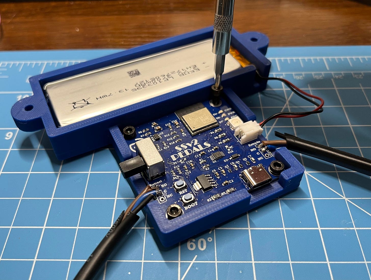
After that, insert your pedal PCB and screw it in using four M3x8mm screws. No nuts are needed for these.
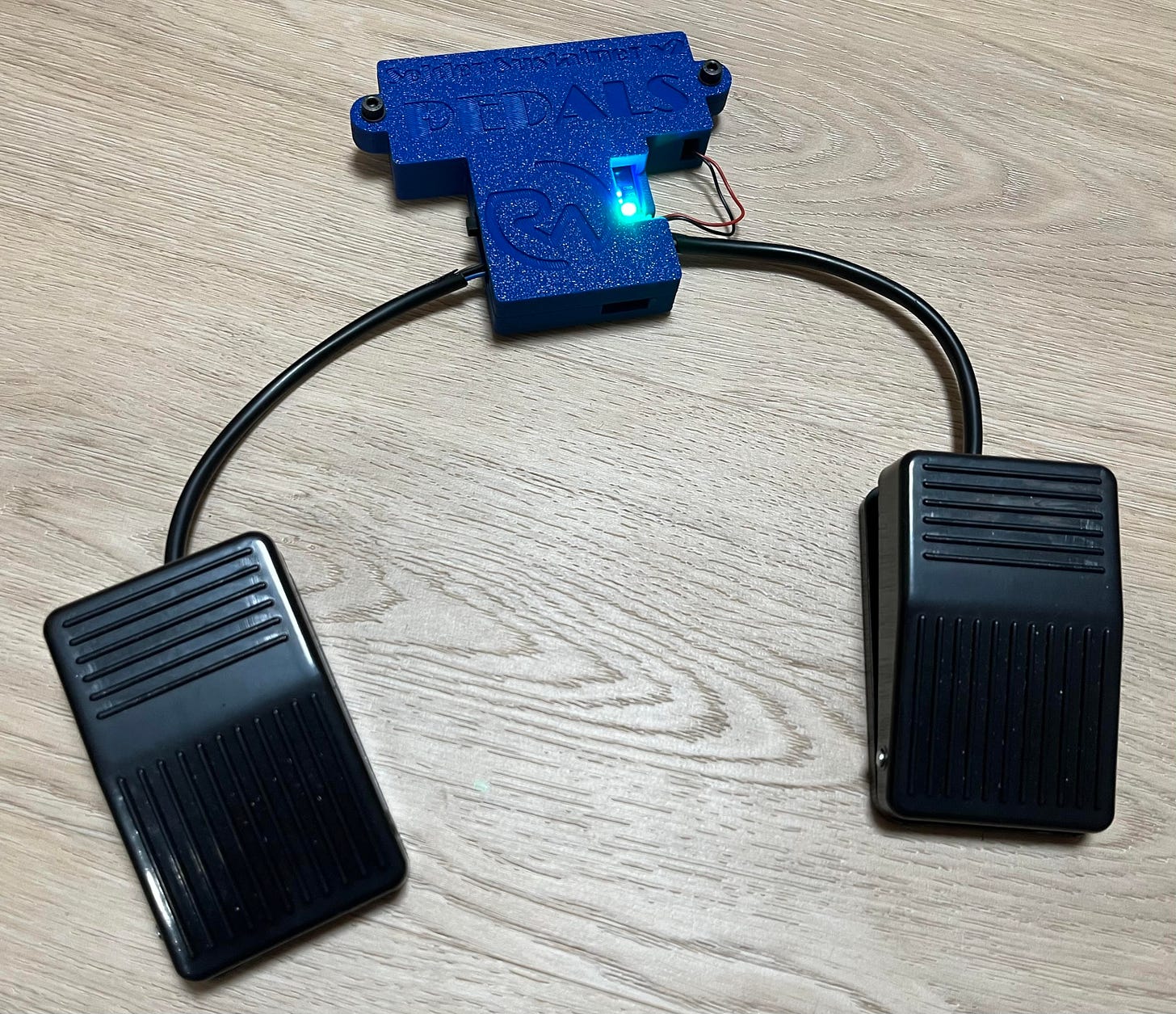
When that’s done, insert two M4 nuts into their slots on the back of the bottom casing and screw in the top piece casing over it using two M4x14mm bolts and some M4 washers.
That’s it!Congrats!
Programming
NOTE: Before uploading any code, you must put the board into bootloader mode. You can do this by holding the boot button > hitting the reset button (RST) > and then releasing the boot button.
- The complete code for the glove PCB can be found here.
- The complete code for the pedal PCB can be found here.
- You will need to change the MAC address of the pedal PCB to match your specific glove PCB. But more on that later!
Let’s run through the main idea of what we want each program to do:
- For the pedal PCB, we need a program to take the inputs of each of our foot pedals and then send those signals wirelessly to our glove PCB.
- For the glove PCB, we need a program to read each signal sent from the pedal PCB. Then, based on those, move our extrusion motor and manage the soldering lights.
- For both PCBs, we also want to read the signal from our ADC IC and map that value to a color for both to display.
If you’d like to learn more about ESP-NOW, the wireless protocol we are using, you can learn more here. The link will also walk you through setting up ESP-NOW and the basics of how it functions if you’re interested.
The links for the other libraries used can be found here:
With that, let’s dive in! I will be programming in the Arduino IDE, which I explained how to set up with ESP32 here. Let’s start with the glove PCB program.
Glove Code: Here’s how it works.
First, we need to import all of the libraries we are using and create an object for our ADC.
#include <esp_now.h>
#include <WiFi.h>
#include <FastLED.h>
#include <MCP342X.h>

MCP342X myADC;
Then, we need to define all the variables and create a data structure to hold our ESP-NOW information.
#define FL_PIN 2
#define BAT_PIN 10
#define NUM_LEDS 3
#define NUM_LEDS_BAT 1

CRGB leds[NUM_LEDS];
CRGB battLeds[NUM_LEDS_BAT];

typedef struct struct_message {
  int a;
  int b;
} struct_message;

struct_message dataRecieved;

const int freq = 260;
const int channel1 = 0;
...
Now entering the setup loop, we need to tell our ACD library which pins to use for the SCL and SDA lines, in addition to configuring communication with the chip. In this case, pin 1 is the data and 0 is the clock.
Wire.begin(1, 0); // SDA_PIN/SCL_PIN

myADC.configure(MCP342X_MODE_CONTINUOUS | MCP342X_CHANNEL_1 | MCP342X_SIZE_16BIT | MCP342X_GAIN_1X);
With that, we can enable our DRV8833 IC and configure WiFi communication.
pinMode(enablePin, OUTPUT);
digitalWrite(enablePin, HIGH);

WiFi.mode(WIFI_STA);
We can then buzz the haptic motor in 500ms intervals if there are any problems configuring communication. This way, the user can be notified of the problem.
if (esp_now_init() != ESP_OK)
{
   buzz(500, 500);
   return;
}
else // Don't buzz
{
   ledcWrite(channel3, 0);
   digitalWrite(bIn2, LOW);
}
If it passes this line, it means communication must be steady. So, we can go ahead and receive the data.
esp_now_register_recv_cb(callData);
Then, we can configure the RGB LEDs to their respective pins and define how bright we want them to be with a value of 0-255.
FastLED.addLeds<SK6812, FL_PIN, GRB>(leds, NUM_LEDS);
FastLED.addLeds<SK6812, BAT_PIN, GRB>(battLeds, NUM_LEDS_BAT);
FastLED.setBrightness(200);
After that, we can configure the different PWM signals to a resolution (0-255) and a frequency. This will be the frequency that drives the H-bridges for our motors. Then, we map a pin to each. We only need three PWM lines, since we only have three directions in which we need the speed to change. Forward and backward on the extrusion motor, and forward on the haptic motor.
ledcSetup(channel1, freq, resolution);
ledcSetup(channel2, freq, resolution);
ledcSetup(channel3, freq, resolution);

ledcAttachPin(aIn1, channel1);
ledcAttachPin(aIn2, channel2);
ledcAttachPin(bIn1, channel3);
pinMode(bIn2, INPUT_PULLDOWN);
Next, we can buzz the haptic motor twice to indicate that everything’s been successful up to this point (250ms on, 250ms off).
buzz(250, 250);
buzz(250, 250);
Now entering the super-loop, we need to start a timer to keep track of when each variable gets updated. This is necessary because the ADC library has some small blocking functions, which would flicker the soldering lights if not properly managed.
unsigned long currentMillis = millis();
We can overcome this, by creating a non-blocking delay with a timer. This makes it so that we only call our ADC functions every 120000ms (or 2 minutes), which is the perfect amount of time to still get accurate/up-to-date battery readings without any interference. To get the correct battery color, we also need to map the ADC voltage to a color value in FastLED. This way, the color will decrease proportionally to the battery voltage.
  if ((currentMillis - previousMillis >= 120000) || checkPower)
  {
    static int16_t  result;

    myADC.startConversion();
    myADC.getResult(&result);

    int ledColor = map(result, 15010, 19161, 0, 190);
    fill_solid(battLeds, NUM_LEDS_BAT, CHSV(ledColor, 255, 255));

    checkPower = false;
    previousMillis = currentMillis;
  }
With this, we’re almost done! Now we just need a big if-else chain to handle the different inputs we could receive from our two pedals.
- If both pedals are on > turn on the soldering lights.
- If the right pedal is on > extrude and turn off the soldering lights.
- If the left pedal is on > retract and turn off the soldering lights.
- If none are on > do nothing and turn off the soldering lights.
- Then, show the color of the LED value (even if it’s off/black).
  if (dataRecieved.a == 1 && dataRecieved.b == 1)
  {
    retract(0);
    extrude(0);
    fill_solid(leds, NUM_LEDS, CHSV(0, 0, 255));
  }
  else if (dataRecieved.a == 1 && dataRecieved.b == 0)
  {
    extrude(255);
    fill_solid(leds, NUM_LEDS, CHSV(0, 0, 0));
  }
  else if (dataRecieved.a == 0 && dataRecieved.b == 1)
  {
    retract(255);
    fill_solid(leds, NUM_LEDS, CHSV(0, 0, 0));
  }
  else
  {
    retract(0);
    extrude(0);
    fill_solid(leds, NUM_LEDS, CHSV(0, 0, 0));
  }
  FastLED.show();
If you’d like to change the color of the soldering lights from white to something else, just change the line fill_solid(leds, NUM_LEDS, CHSV(0, 0, 255)); to fill_solid(leds, NUM_LEDS, CHSV(i, 255, 255)); with i being the color you want from 0-255. This also follows the visible electromagnetic spectrum pretty similarly with red being 0 and 255 being purple.
That’s it for the main code! However, I did make a couple of functions which I will now explain.
The extrude and retract functions work basically by just changing the duty cycle of the PWM signal, each for a different direction of voltage. We can change this direction by alternating which pin/channel is LOW and which is HIGH with the PWM signal.
void extrude(int speed)
{
  ledcWrite(channel2, speed);
  digitalWrite(aIn1, LOW);
}

void retract(int speed)
{
  ledcWrite(channel1, speed);
  digitalWrite(aIn2, LOW);
}
The buzzer works by simply turning the haptic motor on, waiting however long you’d like, and then turning it off, waiting however long you’d like.
It’s okay that this uses blocking delays since it isn’t called in the super-loop.
void buzz(int timeOn, int timeOff)
{
  ledcWrite(channel3, 200); // On
  digitalWrite(bIn2, LOW);
  delay(timeOn);
  ledcWrite(channel3, 0); // Off
  digitalWrite(bIn2, LOW);
  delay(timeOff);
}
That’s all for the glove! Let’s go through the pedal program next.
Pedal Code: Here’s how it works. I’ll be going into less detail this time since a lot of the code is the same as the glove program.
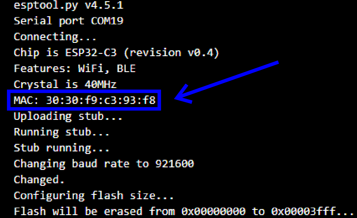
First, let’s assign the MAC address. This is the address to which we will be sending the data (aka., to the glove PCB). This can be found by uploading any code to the glove PCB, and then scrolling up to the chip details.
If this doesn’t work, this tutorial has another method.
uint8_t broadcastAddress[] = {0x30, 0x30, 0xF9, 0xC3, 0x93, 0xF8};
Then, we can structure the data we are sending and handle the peer information.
typedef struct struct_message {
  int a; // Pedal 1 (Extrude)
  int b; // Pedal 2 (Retract)
} struct_message;
struct_message dataSent;

esp_now_peer_info_t peerInfo;
We will need to declare the input pins from the pedals with a pull-down resistor to filter any noise that may arrive from the surrounding circuitry.
pinMode(p1Pin, INPUT_PULLDOWN);
pinMode(p2Pin, INPUT_PULLDOWN);
After that, we can initialize WiFi and check the initialization status if needed.
iFi.mode(WIFI_STA);

  // Init ESP-NOW
  if (esp_now_init() != ESP_OK) {
    // There's a problem
    return;
  }
  else
  {
    // All good
  }
We can also check the status of the delivery with this callback to see if the data was actually delivered or not. This is not needed here but can be useful for troubleshooting later if necessary. Afterwards, we can add the peer (glove PCB) information.
esp_now_register_send_cb(callData);

memcpy(peerInfo.peer_addr, broadcastAddress, 6);
peerInfo.channel = 0;
peerInfo.encrypt = false;
Now, we can read if the two pedal pins are high or low (ON or OFF) to see if they’re pressed or not and assign them to the data variables being sent.
dataSent.a = digitalRead(p1Pin);
dataSent.b = digitalRead(p2Pin);
Then, we send the data.
esp_err_t result = esp_now_send(broadcastAddress, (uint8_t *) &dataSent, sizeof(dataSent));
That’s all!
BOM
This is the Bill of Materials for my Solder Sustainer v2 project!
I’ll put everything that you need to have here so that you don’t have to go scrolling around looking for the links I sprinkled throughout the article.
- All the CAD for this project can be found on my Thingiverse. Everything else including the Gerber files, part list, etc. can be found here on my GitHub.
- The editable STEP files, logo-less STL files, and editable PCB files are available here to paid subscribers. Thanks so much for your support!
- Micro DC motor for the extruder
- 13/64”x13/16” Extension springs (the ones I used I got from this kit)
- Small grooved bearing
- Bronze extruder gear
- Fingerless gloves
- 1.6x6mm Screws (for micro DC motor)
- Velcro strips
- Haptic motor
- Small LiPo battery for the glove
- Bigger LiPo battery for the pedals
- Bowden tube to direct the solder (other colors or brands work too)
- Small but powerful Neodymium magnets
- Some super glue (to mount the magnets)
- Foot pedals
- This was pretty funny since these pedals were wrecked in the reviews for their wires being too thin and short. However, that’s actually perfect for our application haha!
- Optional (if you don’t already have them):
- Mini soldering iron (this is the one I used in the demo video, super cool)!
- Generic soldering iron (this also works if you’re on a budget)
- Solder paste
- Solder (my roll of choice)
- Some nuts & bolts
- Basic screwdriver kit (one of many options)
- Some hook-up wire
Disclosure: These are affiliate links. I get a portion of product sales at no extra cost to you.
Thanks so much for reading! I hope this was a helpful and informative article. If you decide to do the build, please feel free to leave any questions in the comments below. If not, I hope you were still able to enjoy reading and learn something new!
Have constructive criticism or a suggestion for a future project? I’m always looking to improve my work. Leave it in the comments! Until next time.
Be sure to follow me on Instagram! :)
If you feel I’ve given you at least $5 worth of knowledge through my articles, please consider becoming a paid subscriber. I don’t use ads, so I rely on your support to keep going! You will also receive the following benefits.


