Introduction: Build an Arduino Gripper Robot With a DynamixShield.


In this instructable I will show you how to quickly and easily build a remote control gripper robot using and Arduino Zero and a DynamixShield. The DynamixShield is a new add-on for either the Arduino Due, Zero, or Mega that I am promoting for my kickstarter campaign. It is a really cool shield that performs level shifting for the newer 3.3 volt Arduino systems. It has numerous, modular Grove connectors to allow you to quickly plug-in different grove sensors and motors. It also has standard three-pin connectors for analog, digitial, and pulse width modulation signals, making it easy to use with standard servos. Best of all though, is that it has a built in controller for Dynamixel smart servos. This allows you to control Dynamixel AX, MX, and XL servos directly from the shield. When you combine this with the grove modules, it becomes easy to build complicated robots with just 3 or 4 connections.
n this instructable I will use the DynamixShield to control a rolling gripper robot. The core of the frame will be made from Bioloid components and Dynamixel AX-12 motors. This robot was designed based on the probing robot instructions from Robotis, the makers of the Bioloid frames. So a lot of the initial steps are the same as in their guide. However, I have modified their design a good bit. One the bigger modifications is the gripper that is used. They build a gripper with three more Dynamixel servos and other frame parts. I originally built it this way, but it was so front heavy that it would fall over every time I tried to pick anything up. So instead, I switched it out to use the RobotGeek gripper instead. It was cheaper and lighter. The gripper can be moved up and down with a wrist, and opened and closed to pick things up and carry them. The robot will be controlled wirelessly through a XBee grove module and a XBee Commander joystick. So lets get to building!
Step 1: Parts List.
Below is a list of the parts that you will need. I have included links to where I purchased them as well.
Parts List
1. Bioloid FP04 Frame, Qty 1, Unit Price: $6.95
2. Bioloid Nuts & Bolts bag, Qty: 1, Unit Price: $23.40
3. Bioloid F2 Frame, Qty: 1, Unit Price: $1.49
4. Bioloid F3 Frame, Qty: 7, Unit Price: $1.49
5. Bioloid F10 Frame, Qty: 3, Unit Price: $1.25
6. FP04-F13/F14 Wheel Set, Qty: 4, Unit Price: $2.90
7. Bioloid Frame FP04 F55 Cable Holder Pack, Qty: 1, Unit Price: $5.95
8. RobotGeek Gripper Without Wrist, Qty: 1, Unit Price: $24.95
9. LBS-10 11.1V Bioloid LiPo Battery & Case, Qty: 1, Unit Price: $29.90
10. Dynamixel AX-12A smart servo 6-pack, Qty: 1, Unit Price: $224.50
11. Dynamixel 100 mm servo connectors. Qty: 1 pack of 10, Unit Price: $11.90
12. Dynamixel 200 mm servo connectors. Qty: 1 pack of 10, Unit Price: $13.90
12. ArbotiX Commander Joystick, Qty: 1, Unit Price: $59.95
13. Grove XBee Socket, Qty: 1, Unit Price: $6.90
14. XBee 1mW Module, Qty: 1, Unit Price: $24.99
15. Power Connector Cable, Qty: 1, Unit Price: $3.95
16. 538-50-57-9402 Female Terminal, Qty: 1, Unit Price: $0.39
17. 538-70107-0001 Male Terminal, Qty: 1, Unit Price: $0.39
18. 538-16-02-0114 Male Crimp Terminals, Qty, 10, Unit Price: $0.24
19. 538-16-02-0102 Female Crimp Terminals, Qty: 10, Unit Price: $0.24
20. Toggle Switch, Qty: 1, Unit Price: $3.83
21. V2-3.5-1-ND 4mm diameter heat shrink tubing 1', Qty: 1, Unit Price: $1.05
22. Either an Arduino Due, Mega, or Zero. Qty: 1, Unit Prices: $41.11 for Due, $39.97 for a Mega 2560, or $49.40 for Zero.
23. A DynamixShiled that matches the Arduino you choose. Unit Price: ~$35
In addition, you will also need some 24 guage solid or stranded wire, and some solder. So with all of these parts you are looking at around $560 depending on which Arduino board you choose to use.
Step 2: Assign IDs to Your Servos.
Before we start building the robot in earnest, we first need to assign the IDs on all our servos. They come from the factory with an ID of 1. We will use the DynamixShiled to do this reassignment. The software for this robot can be found on my DynamixShield github repository. Clone or download this repo . You will need to copy the folders in the DynamixShield/libraries directory into your Arduino library folder. On Windows this will usually be located in Documents/Arduino/libraries. Once you have done this then load the DynamixShield/sketches/AssignDynamixelID sketch. You can set the current and target ID at the top of the sketch to specify what you want to set the ID to be. Then plug each Dynamixel Servo into the DynamixShield one at a time. Make sure you have a 12V power supply big enough to power the Dynamixel servos, that it is plugged into the DynamixShield, and that you have the power jumpers on for that servo connector. When you plug a Dynamixel servo into the board and it has power then the red LED on the back will flash briefly. You can then upload the new reassign sketch. If it worked, then the servo should be reassigned to the new value and start moving back and forth briefly, and then stop at its center position. Do this for each servo to number them with IDs 1 to 5. Be sure not to move the servo out of its center position during the future steps.
Step 3: Build the Drive Units.


- We will start by putting together the drive units. The robot will use four Dynamixel servos set in continuous rotational mode to move around. Take three of the F3 frame parts. In two of the F3 frames place two N1 nuts in the top left and right nut holes. In the third frame place four N1 nuts in the upper and lower, left and right nut holes. Then for each F3 frame place two F55 cable holders over the top of the nuts as shown in the first image. The cable holders will keep the nuts from falling out when you secure them to the servos.
- For servos 1 and 2 place four N1 nuts into the nut holes on the side as shown in the image. Then place two N1 nuts into the nut holes on the other side as shown in the second image.
- Now carefully place one F3 frame on the top side of each servo and secure it using four S1 bolts. Then place the remaining F3 frame between the two servos and secure each side using four S1 bolts as shown in figure 3.
- Repeat these steps for servos 3 and 4. You should end up with two identical drive units as shown in figure 4.
Step 4: Attach the Wheels.


- Now we will attach the wheels to the drive units. First put the rubber part onto each of the four F1 wheels as shown in image 1.
- Then attach the wheels to each of the four servos of the drive unit using four S1 bolts per wheel as shown in image 2.
- Use three 65 mm Dynamixel Servo cables to connect servos 1 to 3, and to connect 2 to 4. Then connect 3 to 4. The connected a 200 mm cable to servo 1 and leave it free.
- Then attach each drive unit to the one half of the FP04 base frame as shown in image 3 using eight S1 bolts. We will be screwing the bolts into the nuts that we placed into the F3 frames in the previous step.
- Run the 200 mm Dynamixel cable up through one of the holes in the FP04 frame.
Step 5: Attach the Battery Case.


Now lets connect the battery to the back of the robot. We will do this using the LBS-10 case that comes with the Bioloid LiPoly battery and some other frame parts. You will need to two F10 parts and and F3. Place for N1 nuts into a diamond patter in the back of the F3 part as shown in the first image. Then stack the F10 parts together and use four S5 bolts to attach these parts to the back of the F60 frame of the battery. Once you have those connected then use two S2 bolts and two N1 nuts to attach the F3 part to the back of the FP04 frame as shown in the third image. You will need to position it between the motors.
Step 6: Build the Wrist Connector.


Next we will be building the gripper arm. We will use the RobotGeek gripper arm. The official instructions for this can be found here. However, we will be deviating a bit and using a Dynamixel servo for the wrist instead of a standard servo. Because of that we will need to modify their instructions a bit.
1. The RobotGeek gripper arm comes with a metal frame that fits a different standard servo. This will not work directly with a Dynamixel servo. You can slip this frame over the top of a F2 Bioloid frame. Do this and mark two spots where on either side where the F2 frame has holes. Then drill two holes into the metal frame at those spots.
2. Now assemble the other end of the metal frame. Attach the Back Plate and the Back Spacer Plate to the C-Bracket using 4 M2*10 Boltsand 4 M2 Nuts as shown in the first image.
2. Place two N1 nuts into the F2 frame where the holes are located as shown in the second image.
3. Then use two F3 bolts to secure the two frame parts together as shown in the third image.
We now have a wrist frame that we can use with a Dynamixel servo.
Step 7: Mount the Gripper Servo.


- Stack the 9G Spacer Plastic Plate(1/8" thick) , the 9G Spacer Plastic Plate(3/16" thick)and the Gripper Top Plastic Plate together.
- Attach the 9g servo to the 3 plastic plates using 2 M2*16 Bolts and 2 M2 Nuts
Step 8: Mount the Finger Plates.

- Fit the 1/4 x 1/8 Spacers into the center pivot holed on the Left Finger Plate and Right Finger Plate.
- Attach the finger plates with spacers to the Top Plate using 2 M3*10 Bolts and 2 M3 * 15 Standoffs.
- The shiny side of the plastic should face away from the servo, as shown in the photo.
- Make sure that the finger edges create a flat edge as shown in the photo
Step 9: Attach the Gear Plate.

- If you haven't already set the servo position on the 9G servo, return to the Getting Started Guide and set the position to 150°.
- Carefully push the Gear Plastic Plate onto the shaft of the 9G Servo. You will need to attach the gear in such a way that is meshes with the gear on the right finger plate. Make sure that the gripper fingers stay in position creating a flat edge at the top.
Step 10: Add the Back and Finger Standoffs.

1. Connect the 1/4 x 1/8 Spacer to the Gripper Top Plastic Plate using 2 M3*10 Bolts and 2M3 x 15 Standoffs
2. Attach 2 M3*15 Standoffs to the middle holes of the Left and Right Finger Plates using 2M3*6 Bolts.
3. Attach a Fingertip Side Plate to the top holes in each of the Left and Right Finger Platesusing 2 M2*15 Standoffs and 2 M2*8 Bolts
Step 11: Attach Bottom Fingers.

- Attach 2 M3*15 Standoffs to the middle holes of the Left and Right Finger Plates using 2M3*6 Bolts.
- Attach a Fingertip Side Plate to the top holes in each of the Left and Right Finger Platesusing 2 M2*15 Standoffs and 2 M2*8 Bolts.
Lay the Bottom Left and Right Finger Plates on the 6 standoffs. Line the plates up directly over the Top Left and Right Finger Plates.
Use 2 M3*6 Bolts to connect the middle holes of each plate to the standoff underneath.
Insert the Fingertip FrontPlastic Plate into the grooves on the Fingertip Side Plastic Plate.
Fit the Fingertip Side Plastic Plate into the other tabs on the Fingertip Front Plastic Plate.
Use an M3*8 bolt to connect each Fingertip Front Plastic Plate to the Finger Plates and standoffs.
Step 12: Add Back Gripper Frame.


- Fit 2 1/4 x 1/8 Spacers into the bottom holes in the Bottom Left and Right Finger Plastic Plates. Place the other 2 1/4 x 1/8 Spacers over the bottom 2 standoffs.
- Insert the wrist bracket assembly from to the Gripper Top Plastic Plate slots. (Note that this image shows only the standard servo frame. You will need to use the modified one that we built with the F2 Bioloid Frame.)
- Lay the Gripper Bottom Plastic Plate over the gripper.
- Use 4 M3*10 bolts to attach the Gripper Bottom Plastic Plate to the gripper.
- You should now have a gripper arm that looks like the fourth image.
Step 13: Attach Gripper to Wrist.


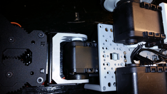
Next we need to attach the gripper to the robot frame.
1. First attach an F10 and an F3 Bioloid frame parts together using four N1 nuts and four S2 bolts. Make sure they are attached perpendicular to each other as shown in the first image.
2. Then place four N1 nuts into the not slots on the bottom of servo 5.
3. Attach the F3 part to servo 5 using four S1 bolts.
4. Attach servo five to the F2 wrist frame using a BU nut and WA washer and a S-B bolt on the back, and four S1 bolts on the servo horn.
5. Connect the whole wrist to the robot frame using two S3 bolts. Screw the bolts into the sockets on the F10 component to secure the wrist.
6. Connect a 200 mm Dynamixel cable to servo 5.
Step 14: Mount and Configure the XBee.


Now we need to configure the XBee to be used with the Arbotix Commander and then mount the XBee socket to the top of the FP04 frame.
1. Follow these instructions on how to configure your XBee for use with the Arbotix Commander.
2. Then follow these instructions on how to assemble and test your Arbotix Commander. You should test the communications between the Arbotix Commander and your Arduino now to make sure it works before enclosing it in the FP04 Frame. You can either use some of the test code in those links, or skip to the programming step and upload the control sketch to test it.
3. If you want to use permanently attached stand-offs to mount your Arduino, then you need to bolt these to the FP04 frame now before mounting the XBee socket. I also discuss another "quick-release" method of mounting that uses magnets later on.
4. Insert the XBee into the socket and then mount it to the inside of the top FP04 frame using two S3 bolts, two SP1 stand-offs, and two N1 nuts. Make sure to place it where it will not come into contact with the battery or gripper frames.
Step 15: Build the Power Cable.


Next we need to build the power cable that will connect the Bioloid LiPoly battery to the DynamixShield and give us a power switch. Image 2 shows the parts we will need for this.
1. The Bioloid LiPoly comes with an extension cable. We are going to use, but change the end connector. Keep the male end on the connector that plugs into the battery, and then cut off the other end. Make sure you not do any of this with the battery plugged in.
2. Strip the ends of those wires and crimp two 538-16-02-0102 terminals to each end. Then insert them into a 538-50-57-9402 terminal. Make sure to keep the order of the wires the same so ground and positive are not switched. This is shown in figure 1.
3. Now cut two lengths of stranded 24 guage wire, one red and one black. Strip both ends of each wire, and then on one end of each crimp a 538-16-02-0114 male terminal on the end. Do NOT insert them into the terminal yet.
4. Solder the other ends of the red and black wires to the switch. Image 3 shows this for the red wire. Make sure you solder it so that when the switch is thrown the power from cable will switch on the power and ground.
5. Now solder on the two wires from the 2.5mm barrel connector to the other posts on the switch. Make sure that you clip off a small piece of heatshrink tubing and place it on the wire before soldering the wires.
6. Once the solder joints on the switch have all cooled, slide the heatshrink tubing down so they completely cover all four of the switch solder points. Then use a hair dryer to shrink the tubing on and cover the exposed solder joints. It should look like image 4 when you are finished.
7. Now insert the male terminal ends into the 538-70107-0001 male terminal. Make sure to keep the polarity the same so that hot and ground are not swapped.
Step 16: Mount the Power Switch.


Now we need to mount the new power switch onto the top FP04 Frame. The frame has two larger holes in it for running cables. However, that hole is just slightly too small for the switch diameter. So I had to drill it out slightly to enlarge it enough so the switch would fit through it. Once you have done that and can fit the switch through, then use the nut and locking washer that comes with the switch to secure it to the frame. Images 1-3 show what this should look like.
Step 17: Finish the Frame.


Now lets close up the frame.
- Insert four N1 nuts into the slots on the sides of the FP04 frame.
- Make sure the all of the cables are run-up through the top of one of the holes in the FP04 frame.
- Push the frame down in place. There are slots to help make sure you have it lined up. Be sure to wrap the cables neatly, and make sure that the switch and XBee socket do not impact anything.
- Then use four S1 bolts to secure it in place. It should look like the second image when finished.
Step 18: Attach the Arduino and DynamixShield.


You can use an Arduino Due or Mega hear, but it it is a tight fit. The image above is using a Due. However, I will show it later on using a Zero. It fits a little better. You can mount this two different ways. I wanted to mount it so I could quickly pop it on and off so I could use the Arduino for other projects as well. To do this I bought some small round magnets at Walmart, along with some double sided tape. I drilled out a hole in four of the magnets, and then partially drilled out a larger hole. This allowed me to use a bolt to connect them to some stand-offs, while having the head of the bolt hidden so the magnet could sit flush. Please see images 1 and 2. You could also just use some stand-offs and place them on the frame. However, if you were going to do that then you should have added the stand-offs for that in an earlier step.
If you are using the magnets then place another set of magnets onto the ones that are connected to the stand-offs of your Arduino. Then place double-sided tape on each of them as shown in image 3. Peel the tape backing from the open side and push it down onto the frame where you want to mount the Arduino. You should now be able to quickly pop the Arduino and DynamixShield on and off of the robot frame.
Step 19: Connect Wires to the DynamixShield.

We need to connect the wires to the DynamixShiled.
- Connect the two Dynamixel cables into two of their slots on the DynamixShield. Make sure you have jumpers on for those two ports so they get power from the board.
- Connect the standard gripper servo to the PWM2 slot in the digital header row. This is the spot closest to the SPI header that is labeled D2. See image 1 above. This connector is not polarized, so make sure you insert it correctly with the brown ground wire on the top of the header row. Also, make sure that jumper J14 that controls the power to the digital headers is set to Vdd and not EXT. The micro-servo uses 5V power, but the Dynamixels on the EXT line use 12V. If you have it set to EXT then you could fry your micro-servo.
- Connect the XBee socket to the grove connector for serial 3, labeled RXD3. The grove connector is polarized, so you cannot insert it incorrectly.
- Insert the power barrel connector into the slot on the DynamixShield. I found it easiest if I ran this cable under the DynamixShield first. Make sure you have the jumper in place to power the Arduino directly from the DynamixShield power.
That is it! With those five connections you are ready to control the robot. Now lets look at how to program the robot.
Step 20: Program the Robot.
You will need to download the source code for this robot from my github repository. Since you already assigned the servo IDs you should have the libraries installed in the correct place. We will be using the DynamixSerial class and the CommanderHS class. DynamixSerial is used to control the Dynamixel servos, while the Commander class is used to process commands from the Arbotix Commander joystick that are coming in from the XBee. The sketch you want to load is found at DynamixShield/sketches/ProbingRobot/ProbingRobot.ino. I will go over the main parts of this sketch here to explain how it works.
1. We start by including the headers for the libraries we will need.
#include //include the servo library to control the RobotGeek Servos
#include "CommanderHS.h"
#include
2. Then we declare some constants we will need that define the IDs for the servos and some min and max values for movements.
//Servo 1: Left, rear wheel
#define LEFT_REAR_WHEEL_ID 1
//Servo 2: Left, front wheel
#define LEFT_FRONT_WHEEL_ID 2
//Servo 3: Right, front wheel
#define RIGHT_FRONT_WHEEL_ID 3
//Servo 4: Right, rear wheel
#define RIGHT_REAR_WHEEL_ID 4
//Servo 5: Claw wrist
#define CLAW_WRIST_ID 5
//Standard Servo Left claw
#define GRIPPER_SERVO_PIN 2
#define GRIPPER_MIN 0
#define GRIPPER_MAX 150
Servo gripperServo; //create an servo object for the 9g FT-FS90MG micro servo
#define WRIST_POS_MIN 312
#define WRIST_POS_MAX 612
#define LEFT_CLAW_POS_MIN 412
#define LEFT_CLAW_POS_MAX 712
#define RIGHT_CLAW_POS_MIN 312
#define RIGHT_CLAW_POS_MAX 612
//#define ENABLE_DEBUG 1
int wristPos = 512; int leftClawPos = 512; int rightClawPos = 512;
int gripperPos = 150; //Start at 150 degrees
int gripperAdd = 0; //Start at 0 degrees add
int currentLeftSpeed = 0; int currentRightSpeed = 0;
3. Then define the DynamixSerial and Commander classes. The DynamixSerial class assumes that it is using Serial1 for communications to the Dynamixel servos. However, if you pass in a hardware serial port here you can override it. This is so the software can be used on custom projects that do not use the DynamixShield. For the Commander class you must pass in a hardware serial class. I have also included a version of the Commander class that allows you to use software serial as well. If you want to use this instead then include the CommanderSS.
CommanderHS command = CommanderHS(&Serial3);
DynamixelSerial Dynamixel(); // or Dynamixel(&Serial1);
4. In the setup, we first start the debug serial connection if debugging is enabled. We then start the commander up at 38,400 baud, and then begin the DynamixSerial class. It defaults to a 1 Mbaud communications rate and the pin that it uses to control the half-duplex of the Dynamixel protocol is set based on the board you are using. So on a Due it is pin 22, but on the zero it is pin 2. However, you also have the option of specifying these parameters in the call to the begin method to override what is used for custom projects. After that is done then it calls a method to configure the servos and commander offsets. I will not go into these methods in detail. They mainly just setup the servos in the correct mode and reset everything to a default position.
void setup() {
#ifdef ENABLE_DEBUG
Serial.begin(57600);
while(!Serial);
Serial.println("Starting setup");
#endif
command.begin(38400);
Dynamixel.begin (); // or Dynamixel.begin (1000000, 22);
configureServos();
configureCommanderOffsets();
}
5. The main loop is very simple. It just calls checkCommander and then delays for 10 milliseconds.
void loop() {
checkCommander();
delay(10);
}
6. The core of the checkCommander method is shown. It first checks if the command has received any messages. If it has then it checks if the buttons for a fast turn have been hit. If not, then it processes the buttons for moving the wheels. It then processes the buttons for the wrist and gripper.
void checkCommander() {
if(command.ReadMsgs() > 0) {
//If we are turning fast then use it to control
//the wheels. Otherwise use regular joystick.
if(!processFastTurns()) {
processWheels();
}
processWrist();
processGripper();
7. You can use the six buttons on the top of the Commander to make the robot turn in place. The three buttons on the right side will make it spin right at different speeds, while the three buttons on the left will make it spin left at different speeds. Also, the right and left buttons at the front of the Commander will make it spin right and left at the fastest speed. We can see this below where we set the left and right wheels to spin in opposite directions with different speed values depending on which button is hit.
bool processFastTurns() {
if(command.buttons&BUT_R1 ||
command.buttons&BUT_RT) {
setLeftWheels(1023);
setRightWheels(-1023);
return true;
}
else if(command.buttons&BUT_L6 ||
command.buttons&BUT_LT) {
setLeftWheels(-1023);
setRightWheels(1023);
return true;
}
else if(command.buttons&BUT_R2) {
setLeftWheels(512);
setRightWheels(-512);
return true;
}
else if(command.buttons&BUT_L5) {
setLeftWheels(-512);
setRightWheels(512);
return true;
}
else if(command.buttons&BUT_R3) {
setLeftWheels(256);
setRightWheels(-256);
return true;
}
else if(command.buttons&BUT_L4) {
setLeftWheels(-256);
setRightWheels(256);
return true;
}
return false;
}
8. If you are not in the fast turn mode, then it checks if you are using the joystick to control the movement of the robot. the processWheels method does this by finding the magnitude and angle of the movement of the walk joystick. The walk joystick is the one on the left of the commander. It uses these values to determine the left and right motor speeds to use.
void processWheels() {
//First lets find the total length of the walkV vector
//This will control the overall speed
int speed = sqrt( (command.walkV*command.walkV) +
(command.walkH*command.walkH) );
float speedNorm = (float) speed / (float) 144.0;
int leftSpeed = 0, rightSpeed =0;
//The angle of vertical to horizontal will control how much turn there is
if(speed > 0) {
float ratio = (float) (command.walkV)/ speed;
float leftRatio = 0, rightRatio = 0;
if(command.walkH > 0) {
leftRatio = sign(ratio) * speedNorm;
rightRatio = ratio * speedNorm;
}
else {
rightRatio = sign(ratio) * speedNorm;
leftRatio = ratio * speedNorm;
}
//The values given back from the arbotix commander are not circular
//They are more rectangular. So if you normalize it then at the max
//forward and reverse settings it is only at about 70% strength. This
//multiplier helps get max speed when going forward or back.
float multiplier = 1;
if( ((ratio >= 0.90) && (ratio <= 1.0)) ||
((ratio <= -0.90) && (ratio >= -1.0)) ) {
multiplier = 1.4141f;
}
leftSpeed = 1023 * leftRatio * multiplier;
rightSpeed = 1023 * rightRatio * multiplier;
setLeftWheels(leftSpeed);
setRightWheels(rightSpeed);
}
9. Next, we check the wrist in the processWrist method. It takes the look joystick vertical signal to control the up/down movements of the gripper arm. The look joystick is the one on the right of the Commander.
void processWrist() {
int wristAdd = map(command.lookV, -102, 102, -10, 10);
if( (wristPos+wristAdd >= WRIST_POS_MIN) &&
(wristPos+wristAdd <= WRIST_POS_MAX) ) {
wristPos += wristAdd;
}
if(wristAdd != 0) {
Dynamixel.moveSpeed(CLAW_WRIST_ID, wristPos, 700);
delay(10);
}
}
10. Then we check whether someone is trying to close the gripper by looking at the horizontal look signal.
void processGripper() {
int gripperAdd = map(command.lookH, -102, 102, -10, 10);
if(gripperAdd != 0) {
gripperPos += gripperAdd;
if(gripperPos > GRIPPER_MAX) {
gripperPos = GRIPPER_MAX;
}
else if(gripperPos < GRIPPER_MIN) {
gripperPos = GRIPPER_MIN;
}
gripperServo.write(gripperPos);
}
}
11. Finally, here is a description of the setRightWheels. This method controls the right wheels of the robot to make them move. The setLeftWheels is pretty much the same, but controls the wheels on the other side.
void setRightWheels(int speed) {
if(speed != currentRightSpeed) {
currentRightSpeed = speed;
if(speed > 0) {
if(speed > 1023) {
speed = 1023;
}
Dynamixel.turn(RIGHT_REAR_WHEEL_ID, 1, speed);
delay(10);
Dynamixel.turn(RIGHT_FRONT_WHEEL_ID, 1, speed);
delay(10);
}
else {
if(speed < -1023) {
speed = -1023;
}
Dynamixel.turn(RIGHT_REAR_WHEEL_ID, 0, -speed);
delay(10);
Dynamixel.turn(RIGHT_FRONT_WHEEL_ID, 0, -speed);
delay(10);
}
}
}
And that is it. There are some other things in the sketch I did not discuss here, but that is mainly for debugging purposes. You can turn on the debugging by uncommenting the //#define ENABLE_DEBUG 1 line at the top. This will print out what is happening as you run the sketch. Use the Arduino IDE to program you the sketch into your microcontroller and then lets run our new robot!
Step 21: Run the Robot.
We are now ready to run the robot. Make sure you have the power cable plugged into to the DynamixShield, and that jumper J30 is in place to allow the Arduino to be powered from the DynamixShield. Also, be sure that jumpers for J17 are on as well. This will make sure that the Dynamixel servos get power. Finally, make sure that the battery is charged and put into its holder, and that it is connected to the power switch. Then flip the switch on. When you do this you should see power on the Arduino, and the gripper and wrist should move to their default positions. Then make sure that the Arbotix Commander is turned on and has a blinking green LED on it. Once you have all of this then you are ready to start driving around. Here is the mapping that shows what each joystick axis does.
- Left horizontal axis: Moves the robot to the left or right
- Left vertical axis: Moves the robot forward and backwards.
- Right vertical axis: Moves the wrist up and down.
- Right horizontal axis: Opens and closes the gripper.
- Right buttons: Causes the robot to spin in place to the right at different speeds.
Left buttons: Causes the robot to spin in place to the left at different speeds.
I hope you have enjoyed this instructable. If you like the DynamixShield and think you would find it useful then please support my Kickstarter campaign so I can produce this board commercially and make it available for your use. If you would like to be notified of new things like this that I am working on then please subscribe to my newsletter.
Thanks,
David