Introduction: CSCI-1200 Final Exam Project 1
In this lab you will be using a potentiometer to turn on and off 5 LEDs. The LEDs will include a fade so that the selected LED is the brightest, while the other LEDs are either off or slightly dimmer.
Hardware required for this project:
1. Arduino Uno
2. Potentiometer
3. 5 LEDs
4. Breadboard
5. Wires/Connectors
Step 1: Add the Five LEDs
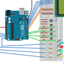
For this project, 5 LEDs will be connected into the breadboard. The LEDs will be connected to the ports on the Arduino that use Pulse Width Modulation (PWM). The ports with PWM are: 11, 10, 9, 6, and 5. PWM is an analog output in the range of 0-255 that is converted to a digital signal.
To connect an LED to the breadboard:
1. Place the LED on the breadboard
2. In the diagram, the bottom lead (-) of the LED is placed directly into the ground rail of the breadboard. A jumper wire can also be used in this step to connect the LED to any position on the breadboard.
3. Connect a jumper wire from a port on the Arduino to the breadboard. Place a 220 Ω (ohm) resistor in the same row as the wire and connect it to the top lead (+) of the LED. For this project, the LEDs are connected to ports: 11, 10, 9, 6, and 5.
4. Repeat steps 1 - 3 to connect the remaining 4 LEDs to the breadboard
Step 2: Add the Potentiometer
The potentiometer will be used to change which LED is selected, which will be the brightest of the 5 LEDs. Depending on the direction the potentiometer is turned will cause the selected LED move either left or right.
To connect the potentiometer to the breadboard:
1. Place the potentiometer onto the breadboard
2. On the side with two pins, the left pin will be connected with a jumper wire to the power rail of the breadboard.
3. The right pin will be connected to the ground rail of the breadboard using a jumper wire.
4. On the side with only one pin, connect the pin with a jumper wire to any of the analog ports on the Arduino. In the diagram analog port A5 was selected.
Step 3: Code for LED Fade
Attached is the 1200_FinalExam_Project1.ino file which contains all the required code to complete this project. The code reads an analog value from the potentiometer, and then using an If-Statement selects the correct LED. The LEDs directly next to the selected LED will be set to a lower level, and the LEDs two passes away from the selected LED will be set to a very dim level. If there is an LED 3 or 4 spaces away from the selected LED, that LED will just be set to off.


