Introduction: Cheapest Retro Game Arcade Controls Encoder Ever!
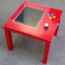
You might have seen the "PIK3A" retro gaming table circulating around the internet. If you haven't seen it, this is a super-cool IKEA Lack coffee table with a monitor embedded in it, arcade controls, and a Raspberry Pi 3 inside running RetroPie so it plays all your favourite classic arcade games.
Anyway, as part of a recent update, I wanted to swap out the encoder that interfaces the arcade-style joystick and buttons with the Raspberry Pi. Being from Yorkshire, I naturally wanted to do this as cheaply as possible.
There are a few different arcade controls encoders out there these days, but this quick and easy hack is the cheapest possible option.
It uses an ultra-cheap knock off SNES-style USB controller for the PC, but it also works (plug 'n' play) on the Raspberry Pi. I ripped out its guts, soldered wires to the button pads, connected the PIK3A table's controls to those wires, and plugged it into the Raspberry Pi.
Note that it's not an original SNES controller. This is a USB joypad -- don't buy the wrong one or it won't work!
It's very responsive (great for button bashing), doesn't require any set up (unless you want to rearrange the buttons, but that's not a necessity), it has six buttons plus START and SELECT/COIN, and it costs less than a fiver. In fact, if you're willing to wait for one to arrive from China, you can build this for less than two quid, making it the cheapest arcade encoder on the entire interwebs.
It'll even work on your PC, and probably your Xbox and Playstation (untested).
Here's a bit more detail.
Step 1: Remove the PCB
Take the controller apart, and remove the PCB.
In mine, there were just five cross head screws underneath. Dead easy.
Step 2: Tin the Button Pads With Solder
Tin the button pads with solder, being careful not to melt them or lift them off the PCB. Be quick and neat with your tinning.
If you look closely, every pad has two connections, and one side is common to every button. There's a big, wide track that connects one side of all the pads together. This is the ground connection. You only need to tin the side of each that isn'tground. It's the one that isn't connected to the big wide track that loops around all the buttons.
Except, that is, for one of the buttons. You're going to connect a ground wire to that side of one pad, which is then automatically connected to one side of all the other buttons, thanks to the big wide ground track that's running around the PCB. Make sense?
Step 3: Solder Wires to the Button Pads
Solder a short wire to each of the button pads you just tinned, including one for the ground side, which will serve all the buttons on the PCB.
You can see my ground wire on the far left hand pad. That's the only button pad that has two wires connected to it.
When soldering your wires, make sure you don't short the two sides of the pad together, or the encoder will think the button is constantly being pressed.
Step 4: Put the Wires Into Connector Block
Strip the ends of your wires, and stuff them into some chock block. I put mine into the connector block in order; so the wires go GROUND, UP, DOWN, LEFT, RIGHT, BUTTON 1, BUTTON 2, etc.
You don't have to, but it makes it easier when it comes to connecting your arcade controls to the other side of the chock block.
Different coloured wires will help you keep track of which terminal in the connector block is which, too.
Step 5: Connect Your Arcade Controls
Connect your arcade controls to the other side of the chock block. Your arcade controls now take the place of the buttons that were on the joypad. In the included image, you're looking at the underneath of my PIK3A table's arcade buttons (on the left) and joystick (on the right).
The wires from those go into the connector block for the encoder PCB. You could hard wire direct to the encoder, but if you ever need to replace it, that'd be a major pain. Better to make it removable.
As with the ground track that runs around one side of all the button pads on the encoder PCB, my arcade controls have a ground wire that runs around one side of all the buttons and joystick microswitches. This way, only one ground wire is needed, reducing the number of wires significantly.
Plug the encoder PCB's USB cable into the Raspberry Pi, and it should work right off the bat!


