Introduction: Combat Robotics Hammerbot
Welcome to our Combat Robotics Project! My name is Vincent Paulines and am a 2nd year Mechanical engineering student in San Jose State University. In our club ASME, we are having a robotics combat competition. With this opportunity I have decided to lead a team for a robot. Thus, for our robot, we decided to make a robot with a hammer weapon design as it would be a fun challenge. For our time in the project, we only have a CAD and are working towards building the robot in the coming year.
Supplies
Drivetrain:
BaneBots Wheel, 1-5/8" x 0.4" (x2)
T40 Hub, 6mm Shaft (x2)
Dartbox V2 Gecko 6mm shaft (x2)
Electrical:
3s 850mAh Tattu Lipo Battery (x1)
15A Dual Brushed ESC (x1)
Flysky 4 Channel Receiver (x1)
Flysky FS-i6 6CH 2.4GHz Radio System RC Transmitter Controller with FS-iA6 Receiver (x1)
5V LED power indicator (x1)
Dartbox Motor PCB 4 pack (x1)
Just Cuz Robotics Switch (x1)
Weapon:
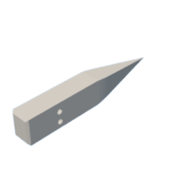
AR500 Steel Hammer (x1)
32 kg-cm 200 degree 25T Spline Servo (x1)
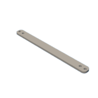
Aluminum Hammer Arms (x2)
3D printed Gears (x2)
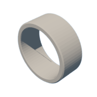
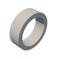
3D printed 1/4" Dia. Bore Spacer (x4)
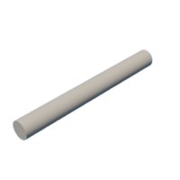
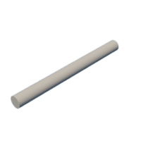
1/4" Dia. 3-1/4" Long Top Shaft (x1)
1/4" Dia. 2-1/4" Long Bottom Shaft (x1)
1/4" Dia. Bearings (10 pack) (x1)
1/4" Dia. Bore Flange (x2)
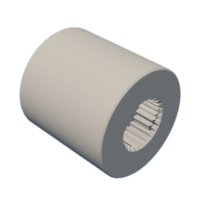
H25T Spline 1/4" Bore Servo Shaft Coupler (x1)
Structure:
3D printed Chassis (x1)
Aluminum Front Plating (x2)
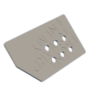
3D printed wedge angle limiter/supporter (x2)
1/8" Thick UHMW plates Top Plates (x2)
3D printed Side Platings (x2)
M6*10 mm Hex Socket Head Screws (x6)
M4*20 mm Hex Socket Head Screws (x10)
M4*10 mm Hex Socket Head Screws (x12)
M3*20 mm Hex Socket Head Screws (x4)
M3*10 mm Hex Socket Head Screws (x4)
Step 1: Weapon Design
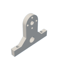
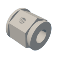
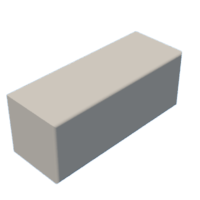
The way the hammer functions is that the servo connected to a shaft will rotate the bottom gear which hence rotates the top gear that the hammer attaches itself to. This mechanism is supported by 3D printed supports on its sides. The hammer itself is made up of AR500 Steel with a pointed end to pierce through opposing robot armor.
The Servo CAD was from the Just Cuz Robotics Website.
Attachments
Step 2: Drivetrain Design
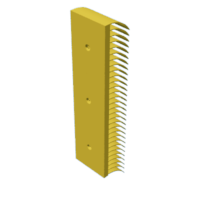
For the Drivetrain, we chose to use a simple 2 wheeled design to keep it simple and to save on weight. However, to circumvent the downside of having the front be wheel-less, we have plastic "skates" screwed at the bottom and thus make movement more smooth.
For the motor CAD, it was from Just Cuz Robotics Website: https://gelburd.autodesk360.com/g/shares/SH35dfcQT936092f0e43f15e6d5c6da9b7a4
Step 3: Electrical Design
This is not an exact wiring diagram but is more of a general guide for where the components fit in the circuit. The battery will connect to the receiver, and the receiver will connect to both the servo motor for the weapon and the Dual ESC which connects to the two drive motors. The LED power indicator and switch will both connect to the receiver. Initially, we were using the large receiver that came with the controller, however when we realized it was too big we switched to a smaller Flysky Receiver.
For the ESC, Motor PCB's, and Switch CADs, they were from the Just Cuz Robotics Website:
https://gelburd.autodesk360.com/g/shares/SH512d4QTec90decfa6e80b5beb04b7d90e9
https://gelburd.autodesk360.com/g/shares/SH919a0QTf3c32634dcfb1bf230f603045e9
https://gelburd.autodesk360.com/g/shares/SH512d4QTec90decfa6eb1192d9fbf31d630
Step 4: Structures Design
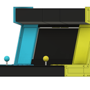
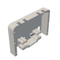
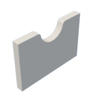
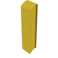
For the Structures design we first started off with the chassis. We decided to have it as one structure instead of components as to reduce bending. Furthermore, for armor there are aluminum plates on mounts at front as to serve as the main protection against spinners. Along with that, we have curved extensions at the sides which are more flexible and can absorb energy compared to a standard flat structure. Finally, we have our wheels covered as to deal with any flippers that aim to flip at the wheels and immobilize the robot.
Attachments
Step 5: Future Improvements to Design
For future improvements to the design, we hope to switch the front plates to front forks. This will save weight and also allow for the robot to act more aggressively. This would be by immobilizing other robots via the forks and then slamming the hammer. Furthermore, we would like to have a battery mount as to protect the battery.

Participated in the
Robotics Contest
















![Tim's Mechanical Spider Leg [LU9685-20CU]](https://content.instructables.com/FFB/5R4I/LVKZ6G6R/FFB5R4ILVKZ6G6R.png?auto=webp&crop=1.2%3A1&frame=1&width=306)


