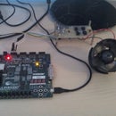
Introduction: Control a Powerful DC Motor With LabVIEW
This article will show you how to control a DC motor power, using an H-bridge made with complementary MOSFET. Avatanjele to the use of bipolar transistors MOSFET is that they have lower conduction losses than bipolar. Orders are given by an ATMEGA328 microcontroller which receives serial data via bluetooth from an application built in LabVIEW by me. This application can be used where we need a complex control engine: electric cars, fans etc..
This article shows just how to control the motor on the direction of rotation and speed of rotation.
Step 1: Let's Talk About H Bridge
My concept is a montage H bridge using only low side mosfet to control engine speed, and high side mosfet is used only to open and close the circuit. For low side mosfet i use IRF3205 that have very low RDS on and low gate charge. For hig side the use IRF5305, which also rds-on small and low gate charge. To switch low side MOSFET I used driver current 2A, MAX627.
According to the diagram, to rotate the electric motor in a sense we need to apply the command on to the point A (5V from ATMEGA328) and low side MOSFET diagonally ordering the PWM duty cycle between 0 and 100% . Variation of duty cycle will vary the speed of rotation. Meanwhile other MOSFET will be placed in logical 0 by the controller.
To avoid skin effect due to motor windings maximum PWM frequency is 10KHz.
This assembly was tested with an engine that had a rated current of 4A and transistors temperature no more than 30 degrees. Additionally you can put the radiator, but the current does not exceed 5A do not think is appropriate.
Step 2: Programing the H Bridge
H bridge is controlled by an Arduino module designed by me with a ATMEGA328 smd.
I have upload this code to this step.
Attachments
Step 3: LabVIEW VI
This is my VI for this project, I upload it to this step. I created in LabVIEW 2013.
Video I hope you understand something. If you have question i will anwser. Regards!


