Introduction: Using Balance to Control a Car


I make this article to show you my last project. This project is about controlling an electrically car from a balance board (Nintendo WII balance board) via bluetooth. This project was presenting on the Student Scientific Session Communication ELSTUD'14 on the University of Suceava and I take the first prize.
This car is a prototype that helped me to see how it works control platform. I started working on another version which will have more powerful engines and duralumin casing.
Step 1: About Balance Board


For control we need a balance board that communicate via bluetooth. I choose the balance board from Nintendo. This board has four pressure sensors named strain gauge force based sensor. Data are read with an microcontroller and are sent via bluetooth to pc. The pc run an application made by me in LabVIEW that can read data form board and send commands like W (forward), A (left), S (backward), D (right), E (stop), R (receive data).
This board was not designed for that kind of job. She was designed for virtual games and start with 2007 for Wii FIT.
Step 2: About the Car

The car is made on a Plexiglas platform has two small DC motors with gearbox. Power supply is a Toshiba laptop battery with four cells placed in series. Engines are given orders by an ATMEGA328 microcontroller SMD, which receives data from the computer as text (LabVIEW) and execute commands that have been programmed. You can read the ambient temperature and battery voltage to a query by the car pc.
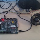
Step 3: Microcontroller Board


The control board is basically a microcontroller board arduino minimized and designed by me and made with SMD components partially.
Attachments

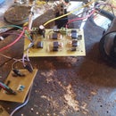
Step 4: Driver Motor Board


The power module for control two DC motors is carried out with the L293D, the chip is capable of a maximum current of 600mA. This is an integrated circuit for controlling continuous two H bridges two different engines have integrated and enable speed control function.
Step 5: Power Supply Board


This module is a high efficiency buck converter to reduce the voltage to 16V (laptop battery) required 5V logic supply all parts of the chassis. It is designed with integrated circuit MAX5035B and is capable of a current of about 1A. The module is built with SMD components.
Step 6: LabVIEW VI

This the VI to control the car, is made by me in LabVIEW 2013.
Attachments
Step 7: Video Prezentation
Look at my feet and followed the car.
This I finish this article, I know it's not so full of information this article, but I can answer questions with the greatest pleasure. Version upgrade will BLDC motor inrunner, ultrasonic radar sensors probably a better processor, and various sensors. Regards !