

Introduction: Controlling LED Matrix Array With Arduino Uno (Arduino Powered Robot Face)


This instructable shows how to control an array of 8x8 LED matrices using an Arduino Uno. This guide might be used to create a simple (and relatively cheap display) for your own projects. This way you might display letters, numbers or custom animations.
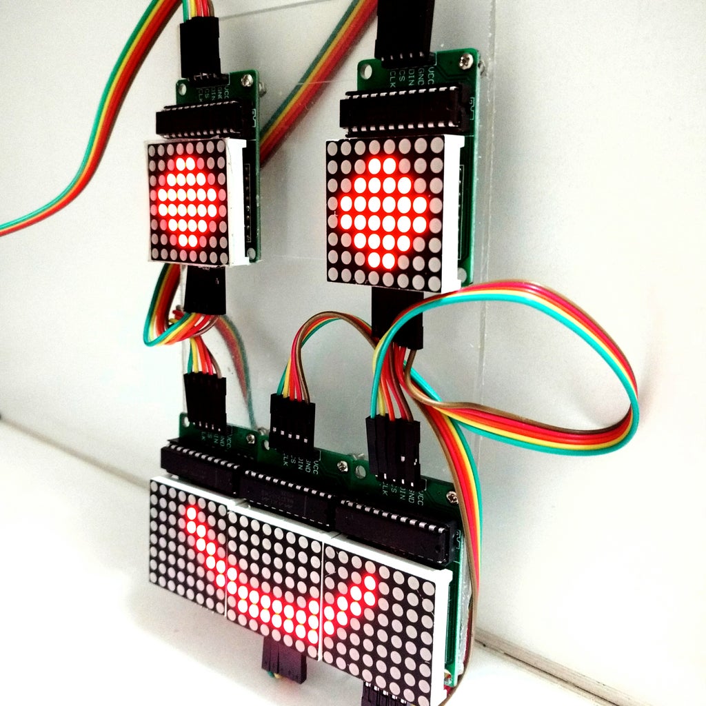
A 5 matrices array used in one of our robot projects ("Robô da Alegria") is used as an example to ilustrate this technology. You might found more about this project in the following links:
https://www.instructables.com/id/Joy-Robot-Rob%C3%B4-Da-Alegria-Open-Source-3D-Printed-A/
https://hackaday.io/project/12873-rob-da-alegria-joy-robot
https://github.com/ferauche/RoboAlegria
https://www.facebook.com/robodaalegria/
Special thanks to the other team members involved in the above mentioned project, responsible for the first version of the code presented in this tutorial:
• Thiago Farauche
• Diego Augustus
• Yhan Christian
Step 1: Components


The following components were used in this project:
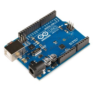
- Arduino Uno (buy)
- 8x8 LED matrix array with MAX7219 driver (x5) (buy)
- Female-to-female jumper wires (4 jumpers of 5 cables each)
- Male-to-famale jumper wires (1 jumper of 5 cables)
- 2mm acrylic sheet (optional for fixation of the components)
- M2 x 10 mm bolts (x20) (optional for fixation of the components)
- M2 x 1,5 mm nuts (x20) (optional for fixation of the components)
- A computer (for compiling and uploading Arduino code)
- Creativity
Notice that you'll need two types of jumpers: female-to-female for the connection between the matrices and a male-to-female for the connection of the firts matrix to the Arduino.
The number of components may vary according to the structure you have in mind.
Step 2: Assembly
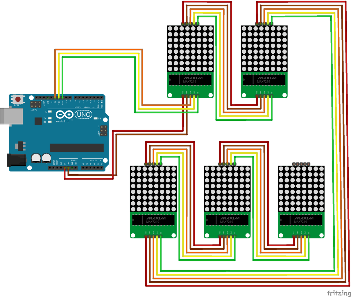

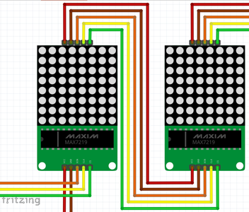
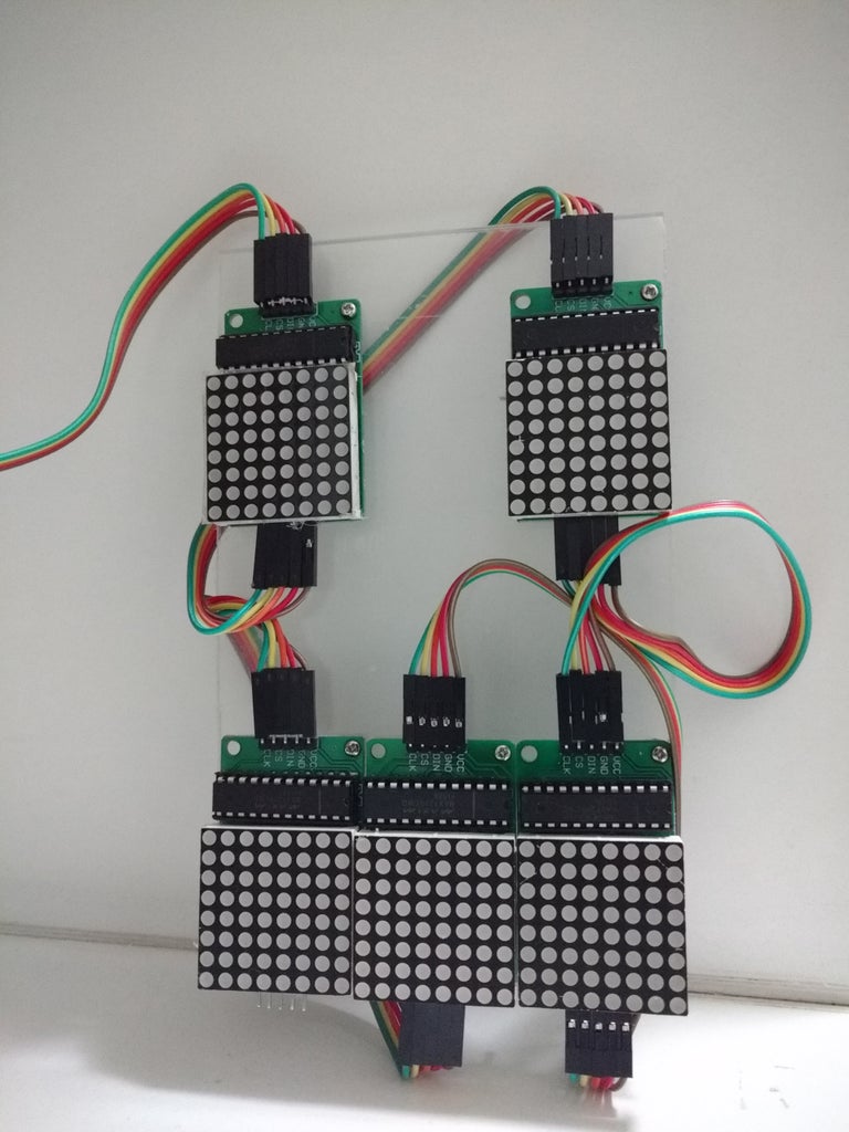
Connect all the componets according to the schematic. You'll need some jumper wires to connect the first matrix to the Arduino, and each matrix to the next one on the array.
Arduino Pinout:
- Arduino digital pin 13 = DIN of the first display
- Arduino digital pin 12 = CLK of the fist display
- Arduino digital pin 11 = CS of the first display
- Arduino 5V pin = Vcc of the first display
- Arduino GND pin = Gnd pin of the first display
You might also want to arrange each display in a given position. For that you might use a acrilic sheet, some bolts and nuts (four for each display) and place each component in position.
No tool is needed to assemble the circuit, but you will need a screwdriver or sharp tool if you wish attach the displays to a surface with some bolts and nuts. In our example, five displays were placed in a face pattern (two eyes and a mouth).
Plug the USB cable to the Arduino Uno board and proceed to the next step.
Attachments

Step 3: Coding

With the latest Arduino IDE version installed, add the LedControl.h library, which is used to control the LEDs.
Download, compile and upload Arduino the code, which is divided in 4 parts:
1. Definition of the eyes and mouth: each eye is configured and a 8-byte array. The mouths are defined as a 24-byte array;
2. Setup: configure displays and start communication;
3. Main: wait for serial communication commands and choose which face will be displayed;
4. Auxiliary functions: functions for setting eyes' and mouth's displays.
setRow function was used to set each row of the LED display. It was used instead of setColumn because it runs eight times faster! This way, the drawings for each display have to be declared rotated 90 degrees counter-clockwise.
setIntensity was used to limit LEDs brightness. It was set as 1 (in a scale from 0 to 15) in order to reduce the power consumption of the modules to a level aceptable by the USB port.
Attachments
Step 4: Usage


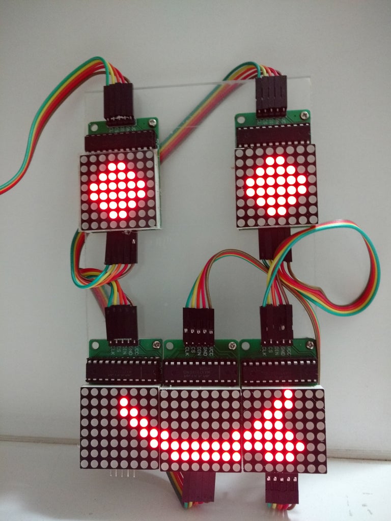


After the upload keep the Arduino connected to the USB port of your computer and open the Serial Monitor.
The code is programmed to display a set of emoticons on the LED face, depending on the message received by the serial port.
The following commands were configured:
For the eyes
- : (normal eyes)
- ; (blink)
- 8 (spooky eyes)
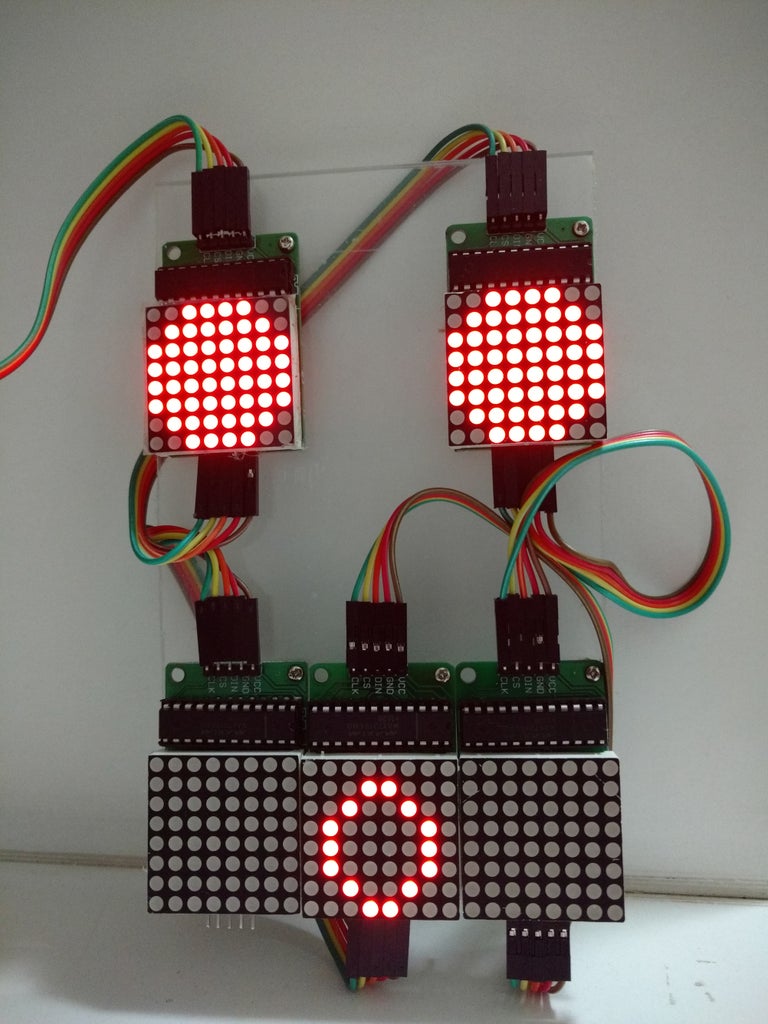
For the mouth:
- ) (happy)
- | (neutral)
- ( (sad)
- D or d (very happy)
- O or o (surprised)
- P or p (tongue out)
Type a pair of characters (one for the eyes and other for the mouth) in the serial monitor, press enter and the displays will be updated according to your command.
You might change the drawings (add new faces for instance) or change the control method (including a bluetooth or wi-fi interface), according to your needs.
Have fun!
