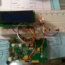
Introduction: Controlling Your LinkIt One Using Light
A great way to start practicing programming is for you to find ways to interact with your microcontroller and for it to emit some sort of action. Today, we'll be using the LinkIt One development board to create music using varying light levels.
This works best in well-lit space, with room for the setup.
Step 1: Material Needed
1. LinkIt One Board
2. Photoresistor
3. Breadboard wires
4. Breadboard/Protoboard
5. Piezo
6. 10K Ohm resistor
7. Preinstalled LinkIt One SDK and drivers
Step 2: Wiring
First, power the rails of the breadboard by drawing 5 volts and ground wires from the 5V and GND pins of the LinkIt One board.
Next, connect the photoresistor (either one of the legs) to the A0 pin of the LinkIt One. This is how the photoresistor will feed input to the LinkIt One. Next, connect a pull-down resistor to the other leg of the photoresistor and have it lead to the ground rail of the breadboard. This should be the 10K Ohm resistor mentioned earlier.
Finally, connect the piezo to the LinkIt One by leading wires to digital pin 8 on the LinkIt One and to the ground rail of the breadboard.
Step 3: Programming
You can download the code through the attachment on this page.
What this code does is take the variable resistance of the photoresistor and change it into varying voltages that are fed to the piezo. This produces differing sounds and tones.
Try raising and lowering your hand over the photoresistor! This blocks out differing amounts of light. The more light the resistor receives, the higher the sound should be!


