

Introduction: Custom Bluetooth Speaker With ZK-1002M Audio Module


Greetings and welcome back! This time, we have something that involves sound and music.
A Small Bluetooth Speaker constructed from scratch using ZK-1002M Audio Module and 3D-printed components.
Based on the TPA3116D2 analog input Class-D audio amplifier IC, the ZK-1002M Bluetooth Audio Module powers this Bluetooth Speaker.
Fusion360 was used to model and 3D print the entire design. The speaker was positioned so that it faced downward.
Down-firing speakers smash the sound against the floor, which then bounces back up to the listening area and improves the sound in comparison to normal speakers.
This Instructables is about how this speaker was built and how you can make it in a few easy steps.
Let's get started.
Supplies
These were the materials used in this build-
- ZK1002M Audio Module (got from PCBWAY's Giftshop)
- 3D Printed Parts Lower and upper body
- 12V Battery Pack with BMS
- M2 Screws
- 4 Ohm Speaker
- Wires
Step 1: ZK-1002M Audio Module


Popular audio amplifiers like the ZK-1002M feature a 3116D2 Power AMP IC, an AUX/USB input, an inbuilt Bluetooth reception IC, and a volume knob.
A kit containing the entire setup is included, and it contains the amplifier board itself, four PCB standoffs and six standoff bolts, a DC Barrel Jack adapter, a plastic knob, a PCB cover, and a tiny screwdriver.
The star or heart of this Audio Module is the TPA3116D2 Power Amplifier IC, which is a popular integrated circuit (IC) designed for use in audio amplifier applications. It is manufactured by Texas Instruments and is widely used in a variety of audio amplification systems, including consumer electronics and DIY audio projects. Here are some key features and characteristics of the TPA3116D2:
- Class D Amplification: The TPA3116D2 is a Class D audio amplifier IC, which means it operates as a digital amplifier. Class D amplifiers are known for their efficiency and ability to deliver high-quality audio with minimal heat generation.
- High Efficiency: This IC offers high power efficiency, making it suitable for battery-powered devices and applications where minimizing power consumption is crucial.
- Output Power: The TPA3116D2 can deliver a substantial amount of power to drive speakers. The exact output power depends on the application circuit and supply voltage, but it can typically deliver several watts to tens of watts per channel.
- Wide Voltage Range: It can operate over a wide supply voltage range, typically from around 4.5V to 26V, making it versatile for various power supply configurations.
- Flexible Input Options: The TPA3116D2 supports various input configurations, including single-ended and differential inputs, allowing it to interface with different audio sources.
- Built-in Protection Features: This IC includes several protection features to safeguard against overcurrent, overtemperature, undervoltage, and short-circuit conditions, helping to prolong the life of the amplifier and connected speakers.
- Configuration Options: The TPA3116D2 is available in various package options, such as HTSSOP, VQFN, and PowerPAD, offering flexibility for different PCB layouts and thermal considerations.
- Audio Quality: It is designed to provide high-quality audio reproduction with low distortion and noise, making it suitable for both consumer and professional audio applications.
- Application Examples: The TPA3116D2 is commonly used in home audio systems, portable speakers, soundbars, and automotive audio amplifiers, among others.
When using the TPA3116D2 in a specific application, it's important to refer to the manufacturer's datasheet and application notes to properly configure and design the amplifier circuit for optimal performance.
Here's the datasheet if you want to know more about this IC-
Step 2: 3D Model


In order to create the design for the body, we must first create a model for the ZK-1002M module. We measure it and create a nearly flawless model in Fusion 360.
We also modeled the battery and the speaker prior to beginning the design.
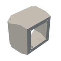
The body will house the speaker and battery, but the BT Module will be placed on top of the 3D-printed body, entirely exposed. The goal here was to position the speaker downward and keep the battery above it.
This entire configuration is distinctive in look due to the ZK-1002M Module's placement on TOP of the body. This will also allow the power amplifier chip's heatsink to get airflow.
The body is created in the shape of a diamond and is further separated into two parts: the main part, which holds the battery and the audio module in place, and the speaker mount.
The whole setup was exported and then 3D Printed using white and yellow PLA.


Step 3: Power Source: Battery Pack


We are using a trio of 18650 lithium cells connected in series with a BMS to create a 12V 2.9Ah lithium battery pack for this project.
A Battery Management system, or BMS, is essential for lithium cells as it monitors and manages the individual cells within a battery pack, ensuring safe charging, discharging, and overall battery health, thus preventing overcharging, over-discharging, and thermal issues that can lead to safety hazards and reduced battery lifespan.
The GND of the BMS was connected to the 0V of the Cell, the 3.7V of the BMS was connected to the 3.7V of the Lithium cell, the 7.4V of the BMS was connected to the 7.4V of the Lithium cell, and finally the 11.1V of the BMS was connected to the 11.1V of the Lithium cell (you may use a tig welding machine here).
When the battery reaches 2.2V, the BMS will cut the output supply, maintaining the cell at that voltage and preventing all cells from undergoing deep discharge. We connect the positive and negative output terminals to PV+ and PV- of the BMS.
I made this BMS myself, but you can find identical packs online. Just make sure they have the right charge and discharge protection, and the voltage should be around 12V.
Step 4: PCBWAY Giftshop


As for sourcing this Audio Module, I got this circuit from PCBWAY's Giftshop
https://www.pcbway.com/project/gifts_detail/MINI_2_50W_Bluetooth_5_0_Power_Amplifier_Module.html
PCBWAY Gift Shop is an online marketplace where you can get a variety of electronics modules and boards for their genuine price, or you could use the PCBWAY currency, which is called beans.
You get beans after ordering something from PCBWAY as reward points, or you can also get them by posting any project in the PCBWAY community.
Check PCBWAY out for getting great PCB service from here- https://www.pcbway.com/
Step 5: Basic Setup


By following the provided diagram, we begin the basic setup.
- First, the positive and negative terminals of the battery pack were soldered to the positive and negative terminals of the DC jack. As this module lacks an input terminal connector, we must connect the battery to the terminals of the DC jack.
- Next, we combine the left positive and negative terminals of the speaker with its positive and negative terminals.
The wiring is complete.
The BT Speaker configuration is then turned ON using the toggle switch that is provided on the Audio Module.
The audio quality is then tested by pairing our phone or computer with the device. At this point, the speaker's sound will be flat and dull because it lacks a proper enclosure to increase the sound quality.
Step 6: Here's a Test Video for Sound Check.
Step 7: Speaker Holder Assembly


The speaker is placed within the speaker holder, and four M2 screws are used to secure it there.
Step 8: Base Assembly


- We keep the battery inside the base assembly and add the Audio Module outside of it.
- Next, we attach the positive and negative terminals of the speaker to the audio amplifier.
- The Audio Amplifier is then mounted using the provided M2 screws and PCB standoffs. The audio module with the 3D-printed base is mounted using four screws and four PCB standoffs from all four sides.
- The TOP Cover PCB that comes with the audio amplifier is added after the audio amplifier is fixed into position.
- Finally, we add Knob in its place to complete the base assembly.
Step 9: Putting Things Together


The final phase of assembly is to permanently fasten the speaker holder assembly and base assembly together. To do this, we slide the speaker holder into the base holder and use four M2 screws. Each edge was secured with four M2 screws.
The speaker is now ready.
Step 10: Result


The end result of this straightforward build is a portable Bluetooth speaker that differs from standard speakers in terms of both construction and design.
Due to the lack of two speakers, the sound quality was only passable during our testing of this speaker using a smartphone connection and a few songs, but it is ideal for podcast listening and everyday use.
The 12V 2.9Ah Battery Pack in this speaker allows for continuous playback for up to 12–13 hours, which is quite practical.
If you wish to construct this speaker yourself, I've included all the necessary files.
That's it for today, guys. A big thank you to PCBWAY for supporting this project. Check them out if you need any low-cost services relating to PCB and PCBA, 3D printing, or even CNC.
Thanks again, and I will be back with a new project pretty soon.
Peace.


![Tim's Mechanical Spider Leg [LU9685-20CU]](https://content.instructables.com/FFB/5R4I/LVKZ6G6R/FFB5R4ILVKZ6G6R.png?auto=webp&crop=1.2%3A1&frame=1&width=306)


