Introduction: Cyberpunk Autoadjust Desk Clock

About: Argentine writer and inventor

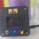
Right now, with Coronavirus and all, it feels sort of dystopian with a degree of breakdown in the social order, so my first idea for a clock was to take old parts combined with some tech in this retro futuristic clock using an old PCB from a water heater, 7 segment display, ESP8266, 2 leds and a buzzer. There are no buttons since the clock obtains the exact time from the web using WiFI. So it's just plug'n play.

Supplies

NodeMCU ESP8266

7 Segment Display 4 digit

2 leds

1 buzzer

1 old PCB from a heater - any old PCB with electronics components will be ok -

1 USB cable

Step 1: Circuits

Connect Display to GND and VIN, D2 and D3

Connect buzzer to GND and D4

Connect leds to GND and D5/D6

Step 2: Code

// CyberPunk WIFI Clock // Roni Bandini @ronibandini #include #include #include #include #include // install NTPClient library from Arduino IDE const char *ssid = "YourSSID"; const char *password = "YourPassword"; const long utcOffsetInSeconds = 3600; // Define NTP Client to get time WiFiUDP ntpUDP; NTPClient timeClient(ntpUDP, "pool.ntp.org", utcOffsetInSeconds); // Module connection pins (Digital Pins) #define CLK D2 #define DIO D3 // Buzzer const int buzzerPin = D4; // leds const int led1 = D5; const int led2 = D6; // The amount of time (in milliseconds) between tests #define TEST_DELAY 100 const uint8_t SEG_DONE[] = { SEG_B | SEG_C | SEG_D | SEG_E | SEG_G, // d SEG_A | SEG_B | SEG_C | SEG_D | SEG_E | SEG_F, // O SEG_C | SEG_E | SEG_G, // n SEG_A | SEG_D | SEG_E | SEG_F | SEG_G // E }; TM1637Display display(CLK, DIO); int completeHour=0; void setup() { // Buzzer pinMode(buzzerPin, OUTPUT); // leds pinMode(led1 , OUTPUT); pinMode(led2 , OUTPUT); Serial.begin(115200); WiFi.begin(ssid, password); while ( WiFi.status() != WL_CONNECTED ) { delay ( 500 ); Serial.print ( "." ); } timeClient.begin(); // Set offset time in seconds to adjust for your timezone, for example: // GMT +1 = 3600 // GMT +8 = 28800 // GMT -1 = -3600 // GMT 0 = 0 timeClient.setTimeOffset(-10800); display.setSegments(SEG_DONE); honk(); delay (1000); } void loop() { timeClient.update(); Serial.print(timeClient.getHours()); Serial.print(":"); Serial.print(timeClient.getMinutes()); Serial.print(":"); Serial.println(timeClient.getSeconds()); uint8_t data[] = { 0xff, 0xff, 0xff, 0xff }; display.setBrightness(0x0f); completeHour=timeClient.getHours()*100; completeHour=completeHour+timeClient.getMinutes(); display.showNumberDec(completeHour, false,4); // waits half a minute delay(30000); ledAnimation(); } void honk(){ tone(buzzerPin, 2000); delay(200); noTone(buzzerPin); tone(buzzerPin, 1500); delay(300); noTone(buzzerPin); tone(buzzerPin, 2000); delay(200); noTone(buzzerPin); tone(buzzerPin, 1500); delay(300); noTone(buzzerPin); } void ledAnimation(){ for(int i=0;i<4;i++){ digitalWrite(led2 , HIGH); delay(100); digitalWrite(led2 , LOW); delay(100); digitalWrite(led1 , HIGH); delay(100); digitalWrite(led1 , LOW); delay(100); } }

Step 3: WiFi Credentials

Before uploading the code to ESP8266, remember to edit your WiFi credentials

const char *ssid = "YourSSID";
const char *password = "YourPassword";

Then you may also need to update your time zone. The code is configured for Buenos Aires, Argentina.

// Set offset time in seconds to adjust for your timezone, for example:
// GMT +1 = 3600 // GMT +8 = 28800 // GMT -1 = -3600 // GMT 0 = 0

timeClient.setTimeOffset(-10800);

Step 4: Demo

Here is a small demo.

More projects at https://twitter.com/RoniBandini and https://www.instagram.com/ronibandini/

Clocks Contest

Participated in the
Clocks Contest