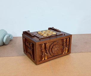
Introduction: DIY-LED Chair Detector
Eric Shan
9D
Kangchaio International School
J05391
Introduction
Hello Everyone! This is my first guide, and today's project will be about a chair detector. To keep it simple, many minors don't push in their chairs and they get scolded by their parents or their teachers for leaving the room messy so to resolve this problem, there are LED lights on the side of this box that will detect if your chair is pushed in or not. If the chair is not pushed in, there will be a red light and if the chair is correctly pushed in there will be a yellow light that will shine, which means it is constantly reminding you to always push in your chair even if your chair is pushed in. These are LED lights so when you leave the room there will be a clear indicator because you will close the lights in the room resulting the LED lights glowing brightly.
Disclaimer
First of all a few safety warnings. Only attempt this build if you know what you are doing. I am not an electrical engineer, I am not to be held liable if something goes wrong. A few dangerous steps/materials are involved and you should be aware of them External power sources are dangerous. The knockoff Chinese components might fail and cause a short. Don’t let them charge unattended, best use an external charger to charge them up, and remove the external battery for storage. If you hit someone or something with them people might get hurt.
Use common sense, be aware of the dangers, read up on your own if you are unsure.
Enjoy the build & have fun!
Step 1: Box Making
Make a box big enough to fit the entire ardunio circuit. Moreover, create platforms long enough so that the Sensors can sit on it. Decorate the box if needed. If you want to get creative measure the dimensions of everything and laser cut it.
Step 2: Programming
My code used in this project:
#define trigPin1 13<br>#define echoPin1 12
#define trigPin2 9
#define echoPin2 8
#define led 11
#define led2 10

void setup() {
  Serial.begin (9600);
  pinMode(trigPin1, OUTPUT);
  pinMode(echoPin1, INPUT);
  pinMode(led, OUTPUT);
  pinMode(led2, OUTPUT);
}

void loop() {
  long duration1, distance1;
  long duration2, distance2;
  digitalWrite(trigPin1, LOW);  // Added this line
  delayMicroseconds(2); // Added this line
  digitalWrite(trigPin1, HIGH);
//  delayMicroseconds(1000); - Removed this line
  delayMicroseconds(10); // Added this line
  digitalWrite(trigPin1, LOW);
  duration1 = pulseIn(echoPin1, HIGH);
  distance1 = (duration1/2) / 29.1;

  digitalWrite(trigPin2, LOW);  // Added this line
  delayMicroseconds(2); // Added this line
  digitalWrite(trigPin2, HIGH);
//  delayMicroseconds(1000); - Removed this line
  delayMicroseconds(10); // Added this line
  digitalWrite(trigPin2, LOW);
  duration2 = pulseIn(echoPin2, HIGH);
  distance2 = (duration2/2) / 29.1;
  //Serial.println (distance);

  if (distance1 >=20
  digitalWrite(led2,LOW);
  }
  else {
    digitalWrite(led,LOW);
    digitalWrite(led2,HIGH);
  }
  if (distance >= 200 || distance <= 0){
    Serial.println("Out of range");
  }
  else {
    Serial.print(distance);
    Serial.println(" cm");
  }
  delay(500);
}
I used Arduino Leonardo, for this project but theoretically, any Arduino supported circuits should work.
Step 3: Soldering
For soldering all you need to do is solder the LED light cables to a longer cable if needed. (Recommended)
Step 4: Testing
Test the result and see if there are any imperfections needed.
Step 5: Assembly
Use hot glue and tape to stick the box together if you used cardboard. Otherwise, you will need hot glue to stick the whole module underneath the table. On the other hand, you could be smart and purchase strong magnets and stick them underneath the table and stick the other half on the module.
Step 6: DONE!
I hope you had fun following along in this DIY tutorial! Thank you! :))
Supplies
1. External Power Source
4. USB micro-B Cable
5. Breadboard
8. 220 Ohm Resistor
9. Cables


