

Introduction: DIY Portable Home Heater


I set out to create something that would keep our homes or living spaces warm, with the requirement that it be compact and portable. After exploring various methods to meet my needs and finding nothing quite right, I decided to create my own solution.
Introducing the smart portable heater: a 400W powerhouse capable of warming up your room in just a few minutes. It features a smart system that displays both the room temperature and the temperature of the airflow it generates.
You can select from various temperature settings and adjust the warmth level to your preference. This device is entirely made through 3D printing, meaning you don't need any special skills to create this handy gadget. I believe it's an interesting addition to any home. Thank you, and enjoy!
Supplies
Items that we need
- 12cm x 12cm Cooling Fan * 1
- M6 Thread bar ( length of thread bar : 13cm) *4
- M6 Bolt * 12
- Hot plate heating coil 2000W *1
- Arduino Nano Board * 1
- DHT11 sensor module * 2
- DC10-60V DC 20A Current Voltage regulator *1
- LM7805 regulator *1
- ON/OFF switch 110V 10A * 2
- SSD1306 OLED display *1
- 65/0.30 copper auto wire : 2m (red and blue)
- 28/0.30 copper auto wire : 2m (blue and white)
- some wires
Tools that we need
- Soldering Iron
- Steel Tweezers
- Wire cutting plier
- Soldering wire
- Soldering Helping Hands
- 3D printer
- Screw driver
3D printed parts


Step 1: Build the Basic Structure


Here, our primary objective is to generate heat, and I have explored several methods to achieve this. One interesting approach that caught my eye is the hair dryer. At its core, a hair dryer operates on a straightforward principle: it houses heating coils through which air, propelled by a fan, is forced. This process effectively warms the air before it's blown out, providing the heat we're interested in.
Following this inspiration, I decided to implement this heating method. I started with a basic sketch of the design, featuring a dual-layer heating element at its core. Below this, I positioned a 12cm x 12cm cooling fan, while the top part of the design houses all the necessary electronics, arranged in a unique shape. Included in these electronics is a display to monitor both the airflow and ambient temperatures. As it’s special shape, we can turn our heated air flow efficiently.
Step 2: Design the Structure With Fusion360


Let's design this. I used Fusion 360 for this job. After spending several hours and adding all necessary features, I came up with this design.
How I design this: Watch this video part
Attachments

Step 3: 3D Print the Models


Alright, let's move on to printing it. I used some tips to reduce the printing time. These tips are applied using the Cura slicer. If you want to learn how to do them, watch this video : https://youtu.be/MWhyCarNPbs
Make sure to insert the nut into the middle part while it's printing. Then, before sealing the holes, ensure you remove any support structure from them.
Step 4: Output of 3D Printing


After a total of 28 hours, I've printed all the parts. Then, I had to perform some finishing operations to achieve this appearance.
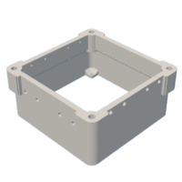
Step 5: Make the Bottom Part


First we need to fix the cooling fan to the bottom part. For it insert M3 brass hot melt insert nuts into the holes in the bottom part.
Next, secure the cooling fan to the bottom part using M3 nuts.make sure to fix it according to air flow direction.
Related video part : Watch this
Step 6: Install the Heating System Part 01


First, I used a hot plate coil as the heating element. How do heating coils work? We know that when current flows through a resistor, heat is generated. Heating coil operates in the same way as a resistor. It has resistance throughout the coil, and when current flows through it, heat is generated just like through any resistor.
Step 7: Install the Heating System Part 02


Now, let's move on to configuring our coil. After some trial and error, I decided on this setup. To ensure safety, I powered the coil with a 12V DC supply instead of 110V. I chose a 3 Ohms coil, which allows 4A of current to flow through according to Ohm's law. By connecting 4 coils in parallel, the total current passing through the coils is 16A.
Ohm's law :
V = IR
12 = I x 3
I= 4A
This can also be understood in another way. When four 3 Ohms resistors are connected in parallel, the equivalent resistance is 3/4 Ohms. Therefore, connecting this to a 12V supply results in a current flow of 16A.
Step 8: Install the Heating System Part 03


I utilized two such parallel configurations, meaning the power supply should provide a total of 32A. Now, let's prepare the coil. First, unroll the coil that I mean increase the gab between each circle. We need a total length that gives us 3 Ohms of resistance. Use a multimeter to measure this resistance and then cut the coil at the correct length.
Now prepare the both ends like this. Which we'll use to connect the 4 coils together. According to this create 8 coils
Step 9: Install the Heating System Part 04


Now, we need to attach these coils to the middle part. However, we can't connect them directly to the middle part's body, because the ends of the heating coils will become hot and could melt the 3D model. To do this job, proper solution is, fix the coils through heat resistance plastics. That's why I'm using Bowden tubes (filament pipes from 3D printers), which are designed to withstand high temperatures without melting. You can see they don’t melt under high temperatures.
Now, let's attach them to the middle part. Cut the pipe into 5mm small pieces and secure them to the holes in the middle part with super glue.
Step 10: Install the Heating System Part 05


Now insert the coils' ends into the prepared holes. Take copper wire with a 1mm^2 cross-sectional area. Measure the needed length and bend it as shown. Insert the coils' ends between the wire pair and bend the end of the heating coils by 90 degrees. Now, solder the copper wire securely.
According to this way, make the other end also. Finally I made two layer heating coil system like this.
Step 11: Fix the Bottom & Middle Parts Together


Now fix the middle part with the bottom part. For it, attach M3 brass hot melt insert nuts to the top holes of the cooling fan. Then insert M3 nut to ensure proper fixing.
Step 12: Make the Top Part's Supports


Cut four pieces of an M6 threaded bar, each 13cm long. Now fix them with the middle part like this. Now insert nuts into the threaded bar and keep them in same level.
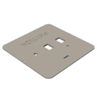
Step 13: Modify the Top Part to Withstand With Heat


Now, take the top part. We need to add an extra layer to this surface because the hot air hitting it could heat the surface continuously, potentially melting the model. Therefore, take an aluminum plate, cut it into the appropriate shape and bend them through the parting line as given in the figure. Then affix them to the surfaces using double-sided tape. The double-sided tape will act as a heat insulator between them. After paste heat insulating tape through the edges.
Related Video part: watch this
Step 14: Fix the Top Part


Attach the top part on the four threaded bars and secure it by adding nuts on the top side. Make sure to keep the major hole of the top part and middle part's wire hole in same side.
Step 15: Make the Electronics Part 01


Next, let's tackle the wiring. First, route the main power wire into the top part. Then, bring the heating coil wires into the top part as well. We need to install the circuit boards inside the top part, but before doing that, create holes in the support columns for the nuts using a hot iron rod. After this preparation, secure the Arduino Nano with screws. Ensure that you upload the Arduino code provided in the next step to the Arduino Nano before fixing it with the top part.
Step 16: Make the Electronics_ Arduino Part


Two two DHT11 sensor modules. remove output pins from the modules. Remove the cover of one DHT11 sensor and place it in the airflow. Then take SSD1306 OLED display, some wires and female headers. Make the circuit give in the figure. Don't directly solder OLED display to Arduino nano. Use female headers to make the OLED removable.
Now upload the code.
To accomplish displaying temperature readings from two DHT11 sensors on an SSD1306 OLED display with an Arduino Uno, you'll need the DHT sensor library along with the Adafruit SSD1306 and Adafruit GFX libraries. If you haven't already, you can install these libraries via the Arduino Library Manager:
- DHT sensor library by Adafruit
- Adafruit SSD1306
- Adafruit GFX Library
// ===================================================================================
// Project:       Two temperature detactor on I²C OLED
// Year:          2024
// Author:        PHYTION
// YouTube:        https://www.youtube.com/@PHYTION1
// Instructables:  https://www.instructables.com/member/PHYTION/
// X(Twitter):     https://twitter.com/PHYTION1
// License:        http://creativecommons.org/licenses/by-sa/3.0/
// ===================================================================================


#include <Wire.h> // Include Wire library for I2C
#include <Adafruit_GFX.h> // Include Adafruit Graphics library
#include <Adafruit_SSD1306.h> // Include Adafruit SSD1306 library to control OLED display
#include <DHT.h> // Include DHT sensor library
#include <DHT_U.h> // Include DHT sensor unified library


// Define OLED display dimensions
#define SCREEN_WIDTH 128 // OLED display width, in pixels
#define SCREEN_HEIGHT 64 // OLED display height, in pixels
#define OLED_RESET    -1 // Reset pin number (or -1 if sharing Arduino reset pin)


// Initialize OLED display
Adafruit_SSD1306 display(SCREEN_WIDTH, SCREEN_HEIGHT, &Wire, OLED_RESET);


// Define DHT sensor setup
#define DHTTYPE DHT11   // Specify DHT model, in this case DHT 11
#define DHTPIN1 4       // Define DHT sensor 1 data pin connected to Arduino pin D4
#define DHTPIN2 5       // Define DHT sensor 2 data pin connected to Arduino pin D5
DHT dht1(DHTPIN1, DHTTYPE); // Initialize DHT sensor 1
DHT dht2(DHTPIN2, DHTTYPE); // Initialize DHT sensor 2


void setup() {
  // Initialize OLED display
  if(!display.begin(SSD1306_SWITCHCAPVCC, 0x3C)) { // Start the OLED display
    Serial.println(F("SSD1306 allocation failed")); // Print error message if initialization fails
    for(;;); // Infinite loop to halt further execution
  }
  display.clearDisplay(); // Clear the display buffer

  // Initialize DHT sensors
  dht1.begin(); // Start DHT sensor 1
  dht2.begin(); // Start DHT sensor 2
}


void loop() {
  display.clearDisplay(); // Clear the display buffer for fresh start
  display.setTextColor(WHITE); // Set text color


  // Read temperatures from DHT sensors
  float temp1 = dht1.readTemperature(); // Read temperature from sensor 1
  float temp2 = dht2.readTemperature(); // Read temperature from sensor 2


  // Display temperature from Air Flow sensor
  display.setCursor(0, 0); // Set starting point for text
  display.setTextSize(1); // Set text size
  display.print("Air Flow: "); // Print label
  display.setCursor(30, 10); // Set cursor for temperature display
  display.setTextSize(2); // Set text size for temperature
  if (isnan(temp1)) { // Check if temperature reading is valid
    display.println("Error"); // Print error message if reading is invalid
  } else {
    display.print(temp1); // Display temperature value
    display.println(" C"); // Append 'C' for Celsius
  }


  // Display temperature from Environment sensor
  display.setCursor(0, 36); // Set starting point for text
  display.setTextSize(1); // Set text size for label
  display.print("Environment: "); // Print label
  display.setCursor(30, 46); // Set cursor for temperature display
  display.setTextSize(2); // Set text size for temperature
  if (isnan(temp2)) { // Check if temperature reading is valid
    display.println("Error"); // Print error message if reading is invalid
  } else {
    display.print(temp2); // Display temperature value
    display.println(" C"); // Append 'C' for Celsius
  }


  // Draw a horizontal line to separate the display sections
  display.drawLine(0, 31, SCREEN_WIDTH, 31, WHITE); // Parameters: start x, start y, end x, end y, color


  // Update the display with all changes made
  display.display(); // Refresh the display with new data

  delay(2000); // Wait for 2 seconds before next reading
}
This code does the following:
- Initializes the SSD1306 OLED display and two DHT11 sensors.
- In the loop() function, it reads the temperature from each DHT11 sensor.
- It clears the OLED display, sets the text size and color, and then prints the temperature readings on the OLED display. If a sensor reading fails, it displays "Error" instead of a temperature.
- It draws a horizontal line to visually separate the readings of the two sensors on the display.
- Finally, it updates the display with the new information.
Please ensure you have the correct I2C address for your OLED display; 0x3C is common, but some displays use 0x3D. You can usually find this information in your display's datasheet or by using an I2C scanner sketch to find connected devices' addresses.
Step 17: Make the Electronics_ Part 02


Now, install the current controller board. As the Arduino nano, make the holes on the columns to fix the circuit.
Then, attach the switches, potentiometer, and OLED display to the lid of the top part. When fixing the Switches decrease the length of the legs by cutting.
Step 18: Make the Electronics_ Part 03


Insert the M2 brass hot melt insert nuts into the top part.
Now, complete the circuit. The circuit diagram is provided in the figure. Ensure you use wires of the proper thickness for each specific task. This is crucial because when we power the heating coils, a total of 32A flows through the main supply wires. Therefore, use wires of the appropriate thickness, such as 65/0.30 copper auto wire. I have labeled the suitable wire thickness that you should include in the circuit diagram.
Finally secure the entire assembly to the top part using M2 nuts.
Step 19: Demonstration


Finally, we need to power our mobile furnace. For this, I've chosen a 12V 40A SMPS power supply.
We can achieve a temperature approximately 15 degrees Celsius higher than the ambient temperature.
How this works? Watch this video : https://youtu.be/glwF60kA
Complete Video : https://youtu.be/glwF60kAOZQ
____________________________
If you enjoyed this tutorial, please consider subscribing to my YouTube channel and following me on other social media platforms. I will keep you updated on my future projects. Your support means a lot to me and greatly encourages my continued efforts.
________________________________
Thank You! -PHYTION

Second Prize in the
Stay Warm Contest


