Introduction: DIY Wood Turner
Tools are love , whether they are hands tools or power tools.But magic happens when they both comes together in action.Well lathe is prefect combination of both categories that can produce end less possibilities when it come across diner.
Ever since I came across a lathe machine, I desire to own one but to do so not only one neat potential investment but you also need to spare a good amount of space in your working area , so to tackle both these difficulties I decided to built myself a lathe machine in the form of miniature wood turner by using commonly available hardware and tools.So hop on to this instructables as we are going to built a miniature wood turner using a DC motor from an old washing machine , some acrylic sheets and a bunch of aluminium tubing.
lets get building...............
Step 1: Extracting Motor
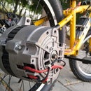
To start with we have got are hands on an old DC motor that is attached to some kind of motor mounting that seems to be a part of washing machine assembly.The motor seems to be quit power full and it produces good amount of torque. We have tested this motor using a 42 volt DC adaptor and motor seems to run quietly so we disassemble the motor from the assembly and remove the pulley and later we remove rust from motor casing using bench grinder.
Step 2: Cutting All the Body Parts
The rail of lathe are made out of 12mm square aluminium tube measuring 12mm wide and 24 inches in length. All the body parts for this lathe are made out of 6mm thick plexiglass sheet. All the pieces are cut down using miter saw and a homemade table saw, they help me to cut them accurately as well.
Step 3: Assembling the Motor Mount
After cutting all the required pieces for the structure, I started assembling motor mount .To make the whole body as strong as possible I started to use cut screw instead of gluing all the body parts together ,so I drilled the holes in each piece and later join them by using 1/4 inches long cut screw ,this gives the whole structure a great strength.
To stop the motor mount sliding on to the aluminium rails I added four cut screws at the bottom of the plate which grips the rails when I tighten them.
The same approach is used for making the other end piece as well all the pieces are together by using cut crew as in the previous step.
Step 4: Attaching the Drilling Chuck
After making structure I have mounted the motor by using two 5mm cut screws. With the motor mounted firmly I also attached 6mm drilling chuck to the motor shaft that is going to grip the rotating piece and the link to that chuck is given below:
Step 5: Assembling the Bearing Holder
Later I join all the pieces of the bearing holder that is going to hold the rotating piece from the other end. Here I am going to drilled the hole and enlarge them by using a file to fit a ball bearing that measure nearly 32mm at the outer side while it can hold 8mm shaft that goes inside the rotating piece. Then the bearing is fitted by using a clap and then bearing holder is slides across the aluminium rails.
Step 6: Bi-Directional Speed Controller
Now to operate this lathe, we are going to make a Bi-Directional speed controller that enables us to control the speed and the direction of rotation by using a single knob only.
For that I have designed the schematic for bi-directional speed controller based on LM324 motor driver IC. To drive large amount of power I have used N and P channel Mosfets. Besides that to ensure smooth operation I have decided to built this speed controller over a PCB rather than a perfboard. So, I have designed a PCB using this schematic. Now to order my PCBs I have visited JLCPCB.com. They are one of the largest PCB manufacturers in China. To order the PCBs I have uploaded the Gerber files and once they are uploaded I have checked out the options that are given below such as quantity, thickness and the colour of the PCBs.
For the first order we can get as low as 2 dollars for 10 PCBs and that includes the shipment cost.
The PCBs arrived within a week and the quality seems flawless as you can see over here. So be sure to checkout their website that is JLCPCB.com.
Now for more details about this bi directional speed controller, the list of the components, schematic and the Gerber files have a look at the one of my previous video. The link for that is given at the top right corner of this video.
Later I have soldered all the components on the PCB as shown on the schematic.
Now with the speed controller ready I have mounted the input wires at with an XT 60 connector on the other side.
While the output wire goes directly to the motor.
Step 7: Adding the Central Pin
Now to hold the rotating piece I have made a pointed tip screw using a bench grinder and a drill machine. And then I tighten the screw on ball bearing in the bearing holder in order to maintain the centre point moving objects.
Step 8: End Results
The project turn out to be a success, as every thing work out pretty well. the only problem we had is that the power is being limited by adaptor due to which we have to use our hoverboard (self balancing scooter) battery that can supply the power needed that can last unto half an hour of continuous wood turning.
The plexiglass structure gives the hole project a neat look and has quiet a bit of strength as not even a single screw came lose even after half hour of continuous run.
I hope you like this project, for more interesting projects have a look at our youtube channel:
https://www.youtube.com/channel/UCC4584D31N9RuQ-aE...
Regards
DIY KING

Participated in the
Woodworking Contest


