Introduction: Digital Clock With Arduino, RTC and Shift Register 74HC595
Hello, everybody!
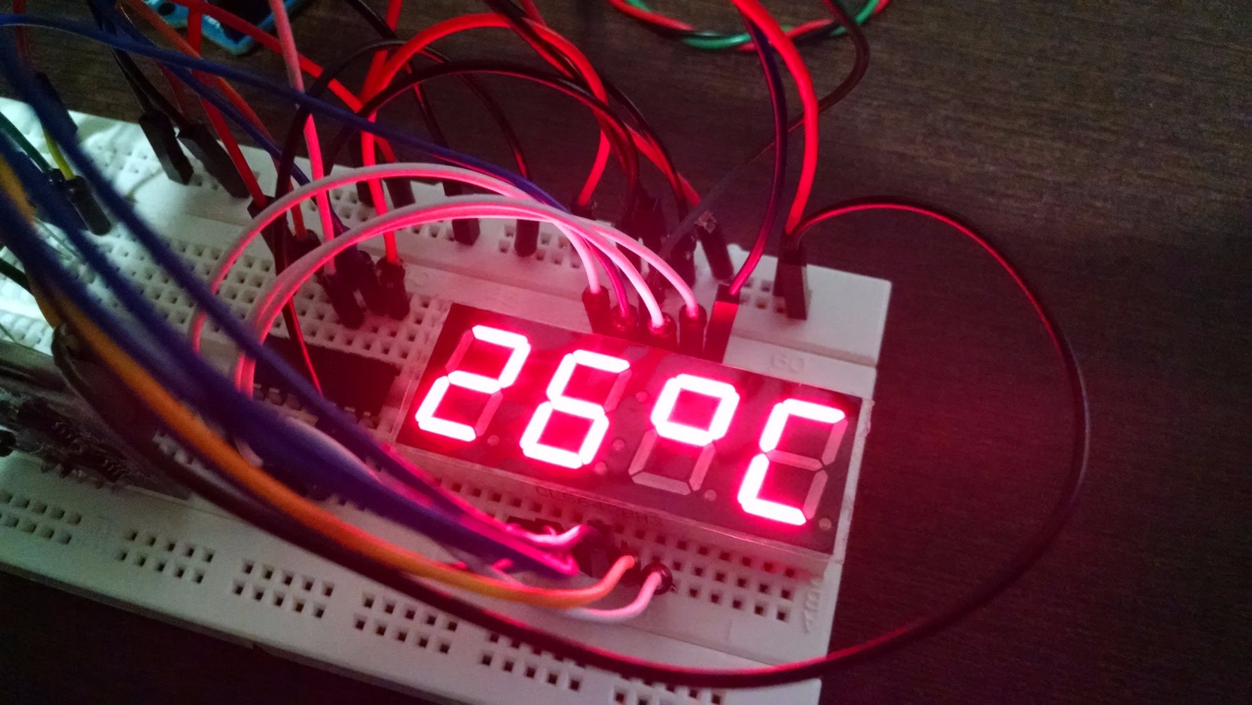
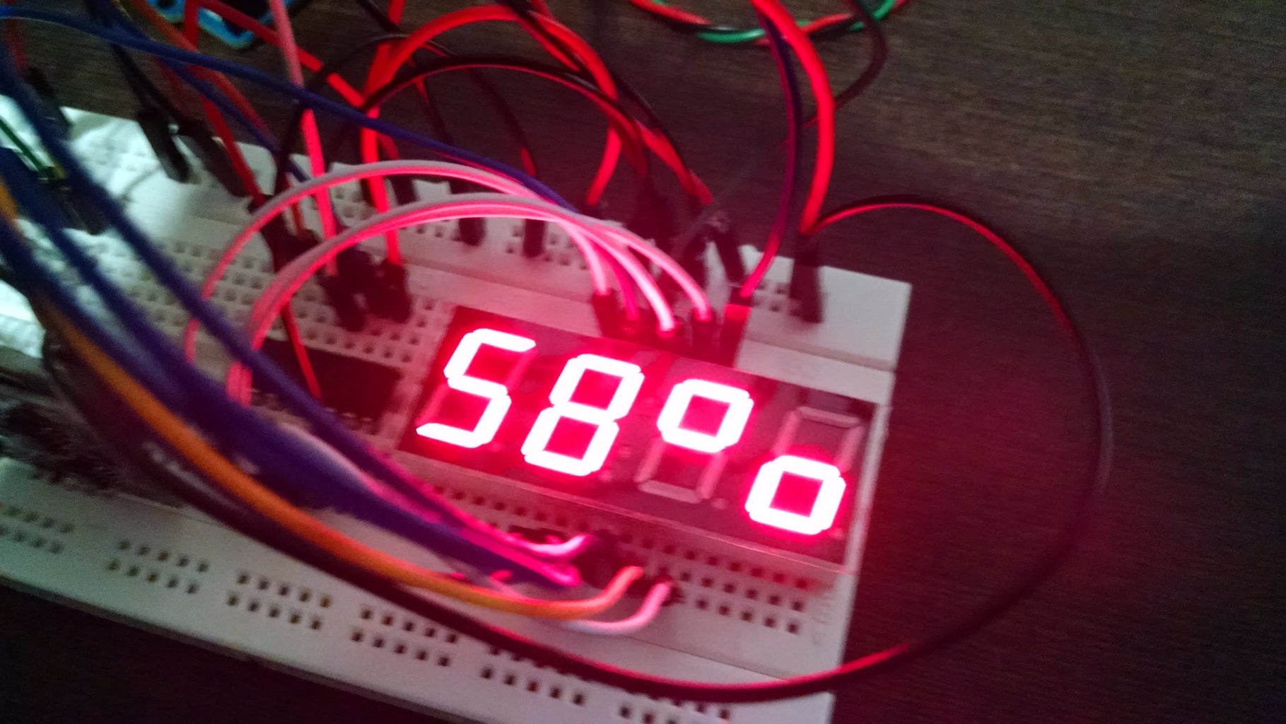
This is my project of a digital clock with RTC (Real Time Clock) using a LED display of 4 digits and 7 segments including interesting features of temperature and humidity. In the control of display I have used an Arduino Uno R3 and 02 ICs of 74HC595 (8 bit shift register with output latches).
The use of shift register is important to save output ports of Arduino. You only need 3 outputs to control the display. With it you transfer serial data into 8 parallel outputs.
There are two breakouts: one for the sensor of temperature (ºC - Celsius / ºF - Fahrenheit degrees) and humidity (% - in percentage) and another one for the RTC.
The assembly is very simple and you just need take care with the wiring. Be patient, follow the schematics and enjoy it.
Step 1: Material
Material list:
- 01 x DS1307 (Real Time Clock)
- 01 x DHT11 (Temperature and Humidity sensor)
- 02 x 74HC595 (8 bit shift register with output latches - 3 state)
- 08 x Resistors of 150 Ohms (Brown, Green, Brown)
- 01 x FYQ-5642BX (Common Anode LED Display 04 digits and 07 segments or equivalent but take care with the pins numbers)
- 01 x Arduino Uno
- 01 x Breadboard
- 01 x Kit of jumpers
Step 2: Assembly
The assembly of components is very simple but you need to follow the schematics with care due to the wire connections. There are 2 shift registers in this project: one to control each segment of the display and another one to control what is the display on.
Important:
If you want to use another kind of LED display, you need to check its datasheet in order to update the output wiring (jumpers) of 74HC595 and also you must update the corresponding logics of Arduino's software.
Step 3: Programming
To run the program on Arduino you need to have the following libraries:
- Time (library for date & time)
- DS130RTC(library for the Real Time Clock)
- Wire (library used to support the RTC)
DHT_Sensor_Libray (Adafruit's library for DHT sensor of Temperature and Humidity)
For the numbering (0 to 9), I have created a table with binary representation of each segment (A to G) that forms the digit as following:
- B01111110 - 0
- B00110000 - 1
- B01101101 - 2
- B01111001 - 3
- B00110011 - 4
- B01011011 - 5
- B01011111 - 6
- B01110000 - 7
- B01111111 - 8
- B01111011 - 9
To show in the LED display the data in sequence of time, temperature and humidity, I have used a "timer" with functions millis() and while().
In this case, each information is presented on the display and after 3 seconds moves to the next one.
Simple and very efficient.
You can apply this function millis() in several different ways to manage the time during the program running.
In many situations you can use it in the place of some timer library.
Another usefull function is digitalWrite(). With this function you can simplify the writting of data into the shift registers.
Take a look on it in the Arduino's home page at http://arduino.cc/en/Reference/DigitalWrite
- How to setup the time of internal clock of RTC module:
1. To update or setup the time of RTC module, load and run the program "SetTime " (you can find it on the library/example of DS1307RTC on Arduino IDE).
2. Reload and run again the program of "Digital Clock".
Following this procedure, the RTC module will keep the right time due its battery pack attached and you do not need to recompile the "Digital Clock" program every time you use it.
Attachments
6 People Made This Project!
- esloch made it!
- AMARNATH S made it!
- merlin10 made it!
- lagsilva made it!
See 2 More
62 Comments
Question 5 weeks ago
Bonsoir
Le montage fonctionne de manière correct et je vous en félicite vivement. Un petit problème : la gestion des points décimaux (DP) lors de la lecture de l'heure. Le registre de décalage des segments (74HC595) ne sort aucun signal sur la broche 15 (Qa), pourtant cette sortie est réservée à l'alimentation des DP des digits 2 et 3. Sans ce signal, le multiplexage ne peut fonctionner sur les points décimaux. En attente de vous lire, recevez mes sincères salutations et encore bravo pour ce montage !!!
Question 2 months ago on Step 3
bonsoir
L'article est très intéressant mais je ne trouve pas le programme dit "relancer le programme de "Digital Clock". Dans l'ensemble de la description, je ne peux le dénicher. Est-ce que je n'ai pas compris quelque chose ?
2 years ago
Oi lagsilva,
Eu sempre acompanho os seus excelentes projetos.
No entanto, ando, a tempos procurando por algum relógio, em especial os feitos com Módulos de Matriz de LED (Max7219) ou mesmo, os feitos com Display 7 Segmentos mas, usando Controle Remoto IR para definir a hora mas, não consigo encontrar. Por gentileza, usando da sua facilidade, faça um relógio desse! Muito obrigado - Daniel
3 years ago
Hi
To increase the brightness or size display, the TPIC6C596 module can be used ??
Question 3 years ago
Olá Silva,
achas que será viável/simples implementar uma função no código e um botão de contacto momentâneo para adicionar/retirar uma hora tendo em conta a hora de verão e de inverno?
Ou seja, no dia em que muda a hora, um toque nesse botão altera a hora, evitando ligar ao computador e enviar de novo o código com a hora actualizada.
Obrigado!
Eduardo
3 years ago
Hi lagsilva, is it possible to get your code for communicating the arduino with the shift registers? I build the circuit following your schematics but I can't code the right instructions to display the numbers using the shift registers. Thank you
Question 4 years ago on Step 3
Sir, Can you provide me the arduino code for this digital clock ???
I want to make it, but I don't no how to program properly.
4 years ago
you have said that you have published another project to set time with push button can you plz share the website link
4 years ago
i need to add led for blinking but if i add blink code in loop ,seven segment switches off when led goes on and if led goes off segment lights on how can i solve this?
4 years ago
Can i change for 12hours time format what should I change code?
Reply 4 years ago
Try to update for the following statements:
hora=hour() %12;
if (hora==0) {
hora=12;
}
Reply 4 years ago
Thank you it's working
4 years ago
Second segment below is not working and sometimes it look like this you can in video what could be problem either circuit or program?
Reply 4 years ago
Probably is a circuit issue. Check the connections and also check individually all LEDs of the display with failure.
4 years ago
thanks for great instructable
in my case dots are not working ...whats the problem?
Reply 4 years ago
Shivam gautam,
Probably the LED display is not exactly the same of this project.
You need to check the electrical diagram of your display and try to identify what pin controls the colon / dots.
4 years ago
Please provide straight forward circuit diagram of the project and how to get following libraries "
4 years ago
What if i using 4 one digit 7segment display?
Reply 4 years ago
You can do it replicating same wiring connections of 4 digits 7 segment display.
4 years ago
technical question : no way to change the 8 protection resistances with only 4 connected to commun anode pins ?