Introduction: Duet Integrated Camera Remote for TimeLapse Video
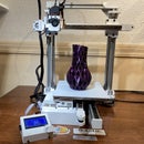
I love the Duet Wifi on my C3Dt/bd but what I did miss was the ability to make timelapse videos like I could using octoLapse. In this instructable I show how I overcame this limitation, rewiring a camera remote that is now controlled by the g-code (take picture every layer change).
The remote I use in this instructable can handle the following cameras.
Canon G10/G11/G15/G12/G1X/SX50/700D/EOS/1200D/1100D/1000D/650D/600D/550D/ 500D/450D/400D/350D/300D/100D/60D Series/70D
Pentax K5/K7/K10/K20/K100/K200
Samsung GX-1L/GX-1S/GX-10/GX-20/NX100/NX11/NX10/NX5
Contax 645/N1/NX/N
Chances are you have one around or can get it reasonably priced on eBay.
This particular remote can operate more than one camera at a time. You can set the channel (one of four) and duplicate it across multiple receivers. allowing you to operate as many cameras as you have receivers.
The remote is operated at 3V which makes it ideal to be powered by any of the available 3.3V outputs on the Duet Wifi (or meastro) board
The image quality is much better than your average webcam. Each image is large enough to create 4K videos (software permitting).
Here is some of the footage created with this setup
(loubie's Aria the Dragon https://www.thingiverse.com/thing:767823)
Supplies
I'll leave the sourcing of a compatible camera to you, although eBay maybe a good place to start. As for the actual remote and components to operate it, you'll need the following:
Neewer DSLR Camera Shutter Release 320ft/100m Wireless Remote Control 2.4G 16CH Transmitter Receiver for Canon: Amazon $19.99
I used Arduino Dupont wiring to connect to the IO pins on the Duet: Amazon $6.98
I used left over wire connectors from the Duet Wifi installation to connect to one of the remaining end stops. Plain dupont connectors would work here as well. Amazon $9.99
for internal wiring I used 22 gauge Silicone Wire Amazon $10.98
Optional:
4 pin JST XHP male/female connector: Amazon $8.99
Single Sided circuit board: Amazon $7.43
Step 1: Opening the Remote
Before taking anything apart I recommend you use the provided batteries that came with the remote and receiver and test if it actually works. Make sure that the jumpers on both the remote and receiver match positions. Once you take it apart it may be harder to return.
Opening the battery compartment for the remote will expose 3 Philips screws that need to be removed. Once the screws are out you can force open the remote (use something like a small flat screw driver in the side to pry it open).
You'll find the the electronics circuit board can be remove without any screws. It just sits in there. At this point take note of the plus and minus connectors as seen in the image above. Connecting the with reverse polarity may damage the remote (did not try this out).
Step 2: Wiring the Remote and Relays
Earlier designs operated using Relays. In my last design, I've removed the need for relays all together. I also simply create a placeholder (RemotePlate.stl and RemoteClamp.stl) that will "press" the remote onto a "knob" that permanently keeps the remote pressed. No more soldering around the remote button needed.
Simply lay the remote circuit into the place holder (remote button down) and attach the remoteClamp over it with 2 #2 3/8" woodscrews and for the holes that go though the remote I use two of the screws that came from the original remote case.
See the wiring diagram above on how to subsequently wire this.
Print out the following two pieces for containing and continuously pressing the button
- RemotePlate_v3.stl
- RemoteClamp.stl
If you do not want to print anything for this build you can solder the 3 corners of the button together which will also cause a snapshot when powering the remote
The remote is powered by the CS5 I/O pin output which provides 3.3v when triggered as Pin 60.
If you want to enclose the entire remote you can print the RemoteLid_v3.stl which will close it all up. The plate and Lid have a placeholder for a 4-pin JST XHP Male/female connector.
Step 3: Taking Pictures Using Gcode
In my setup I've create a set of macros that will take a picture, each macro moving the hot-end away (one keeping it in place). These macros can subsequently be inserted in any print's Gcode The base code for the macro looks as follows:
; store last coordinate in slot 1
G60 S1

; change to relative positioning to move hot-end up
G91
G1 Z40 F9000

; back to absolute positioning
G90

; in this case move X and Y to center bed (this may differ from your printer)
G1 X0 Y0 F9000

; wait for last moves to finish before taking picture
M400

;open the relay to provide power to remote
M42 P60 S255


; wait 800ms for actual relay to trigger (play with this but this is as fast as I could get it to work
G4 P800

;turn off power to remote
M42 P60 S0


; wait x amount of time before moving the head again.
G4 P2000

;return to last stored position (a little slower to not knock over anything
G1 R1 X0 Y0 Z0 F3600
A few things you'll have to experiment with:
Time to leave power on for remote to send signal. I tried faster delays but there wasn't enough time for remote to trigger. 800ms was the sweet spot on mine.
The X and Y coordinates are for you to determine. I happen to have a Delta with a 330mm bed. I created multiple macros:
SnapshotCenter: X0 Y0
SnapshotLeft: X155 Y0
SnapshotBack: X0 Y155
Speed at which you move away your hot-end. I use F9000 which is 150ms/sec. Make sure you put in a speed your printer can handle.
Wait time for the actual picture to be taken varies based on the settings on your camera. depending on those settings and lighting shutter time can vary so you'll need to figure our how fast you can take the picture without the hot-end moving back into the picture. Keep in mind that this time can add serious time to the full print (if you're dealing with thousands of layers).
The next video shows one of my first tests with the timelapse and you can see that there's still frames with the Effector out of position. Prolonging the time after the shutter fixes that (or get better lighting so you can deal with very short shutter times.
Step 4: Adding G-code to Your Print File
I personally use PrusaSlicer for my slicing needs but most slicers have the capability of inserting custom G-Code at each layer change.
Once the macros have been written you can invoke them from the print file with the G-code M98.
In PrusaSlicer you can automatically insert this macro call at each layer change by inserting it under Printer Setting-> Custom G-code in the field "After layer change G-code"
In Cura 4.1 you can select the post processing from the menu and selecting "insert at layer change" script. You'll be asked before or after; select after (otherwise retract won't work).
I'm going to have to rely on my readers here to tell you how to do this with other slicers.
At this point you are good to go. You can start the print.
Before you do make sure you have your camera setting as desired and turned on the receiver(s) on your camera. If you're starting a really long print, maybe put new batteries in the receiver(s). I have not emptied the batteries yet but you hate to have it go out midway print.
Step 5: Creating the Video
There are several software packages that allow you to import images and turn them into time lapse videos. Here is a link to a free one: http://virtualdub.sourceforge.net/ (there's plenty of youtube videos explaining how to use).
I personally use Adobe Premier Elements 2019
Generally in most of these packages you have an option to select the first in a series of numbered pictures and it will automatically select the rest and make it into a clip.
I'm not going into how to make the timelapse videos in further detail. Simply search for timelapse here on instructables and you will find plenty of instructables related to it.


