Introduction: ESP8266 WiFi Notification Lamp


This will be an instructable about creating a notification lamp based on the ESP8266 with the arduino firmware loaded on it.
This instructable assumes you have already loaded the correct arduino firmware on your ESP8266.
Component list:
- 5x WS2812B RGB leds (I used the ones from BangGood)
- 1x ESP8266 ESP-201 (Again from BangGood, this instructable should work with the other ESP models but I cannot guarentee this)
- 1x Breadboard power supply that supplies 3v3 and 5v. (I used the one from this kit, BangGood)
- A soldering iron to solder the RGB leds
- Some wires to hook everything up
- Something to house the project and act as a diffuser for the leds
- A UART <-> USB cable to program the ESP-201
Step 1: Loading the Software


For this project I chose to use an ESP-201 which is a variant of the well known ESP8266 chip. It's supposed to be more breadboard friendly and at the time I was picking them up were cheaper than the other alternatives. If I were to get new parts for this project I would opt for the NodeMCU since it has a much easier programming method.
To get started with this project I have attached a sketch which configures the ESP-201 to act as an notification light for three different services: Twitter, Gmail and Trello. Other services are available but you will have to go through some customizing that I will get into later.
Fire up the Arduino IDE and load up the sketch attached to this step, connect up your ESP module (See this for specific ESP-201 pinouts) and go ahead and hit that upload button following the normal procedure for uploading sketches to a ESP module, there are a lot of guides out there covering this subject such as this one.
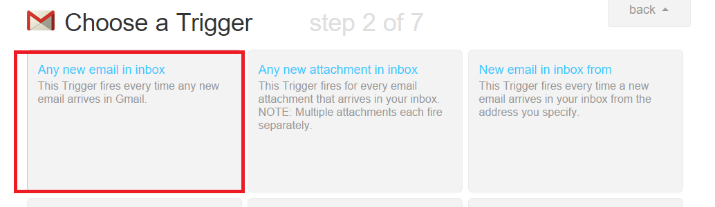
Next up we'll be heading over to IFTTT which will be the site that links our notification light to our Twitter, Gmail and Trello sites. After registering over there, click the My Recipes button at the top of the site. Hit create a recipe to get started. For the This part of the recipe we will be using GMail, IFTTT might ask you to authorize access to your account to check for new emails. Click the "check for new emails" trigger and click create trigger. For the that part of the trigger we will be using Maker to make HTTP requests to our built in API. See the last screenshot for the details of what you need to put in for url.
NOTE:
Currently there are 3 built-in trigger types for: Trello, Twitter and Gmail. You can use the rest of the triggers by replacing the gmail part at the end of the url with either trello or twitter to trigger those notification lights.
Attachments

Step 2: Getting the RGB Leds Ready
Get out your favorite soldering station (I use a cheapass Yihua) and start soldering a strip of 3 WS2028B's together with little bits of wire between them to space them evenly. On the back of the leds you'll see what will hook up to what so it isn't really rocket science. If you want to use more than 3 LEDS don't forget to adjust the arduino sketch to reflect this.
Hooking them up to the ESP-201 is a piece of a cake, in this example I use GPIO_2 on the board to send my data (also can be seen in the sketch and adjusted if need be). If you're lost on what pinouts are which check out the handy pictures over at http://blog.squix.ch/2015/02/esp8266-esp-201-breakout-board-review.html.
Sadly I don't have pictures of me soldering the actual WS2028B's but when I make the next iteration I will be sure to snap some :)
Step 3: Building the Enclosure


Since I just got myself a brand new 3D printer I decided that my enclosure would be one of the first projects that I'd print on it. After browsing on Thingiverse for a while I found a model that I liked that would fit this project pretty well.
http://www.thingiverse.com/thing:912315
I chose this model since I liked the original idea of just a cube lightning up with all the patterns. One thing I changed was that I printed the model smaller so it would not be too bulky on my desktop.
Assembly of the original model should be pretty simple but since I chose to make the model at 1.5x scale it made gluing the different parts together much much harder. In the end I ended up using a combination of tape and glue.
The Thingiverse site itself has more detailed instructions on putting the cube itself together. I'll focus on the part of adding the prepared internals for our smart notification light. Since the scaled down version is a bit harder to fit everything into it is a smart idea to first add all the internal components before you completely build the cube, I also left the top open to work on the internals if I really have to.
Hooking everything up is relatively simple, The datawire of the 3 connected RGB leds goes to GPIO_2 on the ESP-201, the plus and negative go to the 5 volt side of the breadboard power while the ESP-201 power and ground pins go to the 3.3v side. Take note that you don't swap these or bad things will happen to your brand new project!
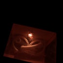
Now go and send yourself an email and you will the pretty colors in your cube light up!


