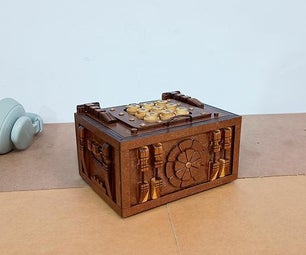
Introduction: Easy Locker Lights
This project is easy enough for Arduino starters. It might need some skills of crafting and understanding how buttons work, but it'll all be explained in the steps below.
I got my inspiration from https://www.instructables.com/id/DIY-Colorful-Pict... .
Step 1: Prepare Materials
In this project, you will need.....
4 LED Lights
1 Arduino board
1 Breadboard
1 Yellow Resistance (Brown, Black, Brown, Gold)
1 Blur Resistance
Plastic Wrap
Tapes
Long Connecting Wires
Wires
1 Button
1 Power Bank
Un-wanted magazine (or something like that)
Step 2: Making the Light Shield
First, you'll have to roll up your un-wanted magazine into the size you want for your locker light, then wrap the plastic wrap around it for at least five times.
After that, roll some tape on it to secure and maintain shape so when you take out the magazine, the plastic wrap won't collapse.
Then try to take the magazine our, if you can't take it out, use a scissor to cut the magazine so it would be easier to take out (DO NOT CUT THE PLASTIC WRAP AND TAPE)
Step 3: Assemble the Circuit 1
In this section, let's connect the circuit for the lights!
Use D-pin 9, 10, 11 and 12 as the inputs for the lights, connect the positive side of each light to the pins with the long connecting wires. Then connect "GND" to the breadboard so the breadboard has a place to connect negative electrodes. Use the long connecting wires to connect the negative sides of the LED light with negative electrodes. Remember to use resistance instead of connecting straight with the negative electric current.
Do this for all 4 LED Lights.
Step 4: Assemble the Circuit 2
Now, let's add the switch button on. This changes the mode of the light determines if the light would be shining or still.
Connect "5v" on the Arduino board to the positives on the breadboard. Use D-pin 2 as the main detector see if the button is pressed or not, so connect it to the breadboard anywhere you want (but do not connect it with the lights). After that, connect the blue resistance on the breadboard from the negative row to the same row as where the D-pin 2 is. Then a leg of the button to the same row and the other on the Positive electrode row.
Step 5: Coding Part
You can try to write the code yourself first as a challenge. When the button is pressed, the lights shine one by one shimmering, when it's not pressed, it shines still.
Full Code: https://create.arduino.cc/editor/dora_the_explorer...
Step 6: You're Done!!!!
Finally, when you finished coding and it works then your done!!!!!! Congratulations!!!! If not, try to find the problem in your system, there might be the problem on the breadboard~


