Introduction: Exercise Assistant A.K.A. "Treadmill Buddy"
This Instructable describes how to build a device that guides the user through a timed workout routine on an exercise treadmill. The impetus for this project arose last year after a surgical procedure and cardiac rehabilitation program that involved 30 1-h sessions of monitored exercise. Each session included a 25-min treadmill routine during which the grade and speed of the treadmill over time was specified on laminated forms. As my fitness level improved, the assigned routines became progressively more challenging in terms of the energy cost in metabolic equivalents (METS). One MET is defined as the amount of oxygen consumed while sitting at rest. The goal of rehab was to get me up to a routine that required a peak energy expenditure eight or more times the resting level (i.e., 8+ METS).
For my rehab graduation ceremony, they handed me a Certificate of Completion and photocopies of the treadmill routines (calibrated according to peak METS) in hopes that I would maintain and further improve my fitness level in a local gym. Initially, I followed the routines using pictures on my phone. Eventually, however, I decided to create the battery-operated device described here, which displays the target grade and speed of the treadmill during every minute of the session.
The heart of this device is the LILYGO T-Display ESP32-S3 microcontroller, which has a 1.9-in color LCD display, two pushbuttons, and built-in lipo battery-recharging capability (500 mA per hr). Using one of the pushbuttons, the program sketch allows the user to select from 7 different 25-min treadmill routines that differ in their approximate peak METS value (ranging from 4.5 to 10 METS). Pressing the other pushbutton will start (and pause) the session. The display shows the cumulative session time (minutes:seconds), as well as the current time window (in minutes), target grade (% incline), and target speed (mph) in white font. In a different font color (red), the display also shows the target grade and target speed during the next time window. When the session times out, one of several end-of-session messages is randomly displayed. Finally, to maximize battery life, the display sleeps after 60 sec.
Supplies
This project uses the following supplies:
- LILYGO T-Display ESP32-S3 1.9 inch ST7789 LCD Display ($13.99)
- 2-pin connector for lipo battery (comes with LILYGO T-Display)
- Lithium Ion Polymer Battery - 3.7V 400mAh ($6.95)
- SPDT panel mount slide switch (~$0.08 each)
- Two (12) 2/56 x 4 mm screws and nuts
- Wire, solder, heat shrink, hot glue sticks
- PLA filament for 3D printer (any color)
Step 1: Tools
I used the following tools:
- wire cutter
- wire stripper
- needle nose pliers
- hot glue gun
- soldering iron
- 3D printer
Step 2: Print 3D Parts
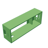
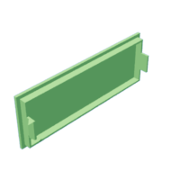
The pictures show the 3D printed parts. All parts were designed using Fusion 360; the STL files can be downloaded below.
- Box (PLA): The enclosure for the LILYGO T-Display was printed without supports at a 0.25 mm layer height (20% infill).
- Snap-fit Box lid (PLA): The snap-fit lid was printed without supports at a 0.25 mm layer height (20% infill).
- Pushbutton inserts (PLA): The pushbutton inserts were printed without supports at a 0.18 mm layer height (100% infill). The green rectangular feature below the buttons was included as a base plate to facilitate adhesion to the printer bed; wire cutters or scissors can be used to separate the buttons from the base plate. Only two of the inserts are needed for this project.
Step 3: Solder Switch, Battery & Connector
Only a few soldered connections are needed for this project (see diagram and picture).
- Use the wire cutters to remove the large JST connector connected to the lipo battery.
- Solder the positive (red) lead from the battery to the common terminal on the slide switch. Since that lead was relatively short, I extended it using another piece of red wire.
- Solder the red lead from the small battery connector (supplied with the T-Display S3) to the normally open terminal on the slide switch.
- Solder the negative (black) lead from the battery to the black lead on the small battery connector.
As can be seen in the picture, I covered all the solder connections with heat shrink to avoid short circuits.
Step 4: Mount Components in 3D Printed Box
Mounting the components is quite simple (see pictures).
- Insert the T-Display into the back of the 3D-printed box such that the USB-C connector and reset button line up with the holes in the side and bottom of the box.
- To hold the microcontroller in place, apply hot glue to the corners of the board as indicated by the blue circles in the picture, making sure the glue overlaps with the sides of the box.
- Connect the JST connector to the battery socket above the USB-C connector on the back of the microcontroller. This connector is polarized and should be inserted with the black and red leads oriented as shown in the picture.
- Mount the slide switch to the end of the box using the 2/56 screws and nuts.
- Carefully pack the battery and attached wires into the back of the box (see picture) and snap the box lid into place.
Step 5: Setup Arduino IDE
In addition to downloading the Arduino IDE 2.3.2 to your computer, you will need to install the files for controlling ESP32 boards (using the IDE's Boards Manager) and two libraries (using the IDE's Library Manager).
- Download/Install the Arduino IDE: HERE and install on your computer (Windows or Mac OS).
- Install the ESP32 Boards Manager: Open the IDE and click on the Boards Manager icon (just below the folder icon in the left column). Search for and INSTALL esp32 by Espressif.
- Install the U8g2 fonts Library: Open the IDE and click on the Library Installer icon (just below the Boards Manager icon). Search for and INSTALL U8g2 by oliver when you find the current version of the library.
- Install the Arduino_GFX_Library: Open the IDE and click on the Library Installer icon (just below the Boards Manager icon). Search for and INSTALL GFX Library for Arduino by Moon when you find the current version of the library.
Step 6: Upload the Program Sketch and Test
- Download/Open the Treadmill Buddy sketch: Download TreadmillBuddy.ino, Workouts.h and config.h to your computer and open the program sketch by double-clicking on the icon for the file with the "ino" suffix. You may need to add the suffixes to these filenames after downloading. The first time you try to open the .ino file, the IDE will ask you to put this sketch in a folder, which you should do. Then, drag the Workouts.h and config.h files into the same folder. The next time you open the sketch file (from inside the folder), the IDE will load all 3 files, which can then be accessed by clicking the tabs at the top of the IDE window.
- Connect the LilyGo T-Display-S3 board to your computer with a USB-C cable.
- Select Board and Port: Click the downward caret to open the dropdown menu on the IDE menu bar at the top of the IDE window. Then click "Select other board and port...". In the new popup menu, select "LilyGo T-Display-S3" and the appropriate USB port; click OK when finished.
- Verify the sketch to check for errors: Click the "Verify" icon in the IDE menu bar. The IDE will then attempt to compile the sketch, which should result in no error messages. Correct any errors before continuing.
- Put the LilyGo board in flash mode: To prepare the microcontroller for uploading the code, press and hold down the pushbutton in the lower right corner, befow the USB-C connector. While holding that button down, press and release the board's RESET button, located on the bottom of the right-hand corner of the board.
- Upload sketch from computer to the LilyGo T-Display-S3 board: Click on the "Upload" icon in the IDE menu bar. The IDE will compile the sketch again and upload the compiled code to the ESP32-S3.
After the IDE indicates that the upload is finished, press and release the RESET button to start the program.
Step 7: How It Works
Note: To recharge the battery, push the slide switch to the "ON" position and attach a USB-C cable to a 5V power source. Assuming you don't push the button to start the timer, the display will go to sleep after 60 sec while recharging.
Step 8: Closing Thoughts
To modify any of the workout routines or add new ones, you can use the Arduino IDE to edit the "Workouts.h" tab. Then save, re-compile and upload your edited code. Hopefully, the sketch comments provide sufficient guidance on how the METS list is organized.
With relatively minor code modifications, the device could also be used to guide workout routines on other types of exercise equipment (e.g., elliptical, stationary bike).
Furthermore, to automatically log your exercise sessions, the ESP32's Wi-Fi capability could be used to store the date, time, duration and other information about your workout to a cloud-based database or to post your exercise efforts on social media.
For those interested in learning more about METS, this publication contains several tables listing estimated METS values for many different household and recreational activities. Also, a METs calculator for walking and running treadmill workouts can be found at this link.
Finally, if you're not into exercising, you can always re-purpose the enclosure described here for a different microcontroller project using the LilyGo T-Display ESP32-S3 (e.g., counting calories)...

This is an entry in the
Making Time Contest


![Tim's Mechanical Spider Leg [LU9685-20CU]](https://content.instructables.com/FFB/5R4I/LVKZ6G6R/FFB5R4ILVKZ6G6R.png?auto=webp&crop=1.2%3A1&frame=1&width=306)


