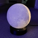
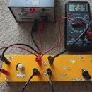
Introduction: Exoplanet Transit Demo Apparatus
Since I was a kid, I was into space and astronomy. Recently I have also discovered passion for 3D printing, that allowed me to bring to life astronomy related projects. In this Instructable, I will show you how to make a model of a Star system with planets, and the principle of Exoplanet detection using transit method.
Kepler telescope finds planets by looking for tiny dips in the brightness of a star, when a planet crosses in front of it (transit across the star). Thanks to that method astronomers discovered many stars with exoplanets. Quite few of them are Earth type planets.
I have designed and made a model of star with two exoplanets which move independently. Then I made a detector (which is a crude equivalent of Keppler telescope apparatus), so you can take readings and learn about transit method yourself.
Supplies
- 2 x Arduino Nano
- 2 x 9V battery
- 2 x 9V battery clip
- BYJ48 with ULN2003 stepper motor
- Arduino SD card module
- Micro SD card (FAT32 format)
- 15mm LDR (light dependant resistor)
- 20k potentiometer
- 4.7k potentiometer
- Push button
- 2 x Mini on/off slide switch
- Equipment wire
- PLA
- Solder
- Super glue
- 3 x large washers
- Cocktails sticks
Tools:
- 3D printer
- Wire cutters
- Screwdriver
- Soldering iron
Software:
- Cura
- Arduino IDE
Step 1: CAD Design
It took me almost one day to design the prototype in Fusion 360. I had to come up with solution how to drive two planets independently, as I wanted to make something slightly more complex than just one planet system. Having two planets opens a lot more scenarios to investigate.
When I have finished designing prototype, I run a quick simulation in Fusion
and then I made few small adjustments.
First I've added holes on the planets arms so you can change the distance from the star to the planet. I've also made few different size planets and I've added a push button so you can change the rotation direction.
NOTE: For more information about 3D printing settings and slicing please check out one of my previous Instructables: https://www.instructables.com/id/Color-Instrument/
UPDATE 14/05/2020: As someone correctly noticed inner planet should move faster than outer planet, so I've changed the gears and uploaded new version marked as '_V2.0'. There are 4 updated parts, Planet1_part1, Planet1_part2, Planet2_part2 and motor_cog
Attachments
 Exoplanet Transit Demo Apparatus - Step #1
 LDR_case.stl
 Planet_1_arm_part_1.stl
 Planet_2_arm.stl
 Star_holder.stl
 Star.stl
 pot_knob.stl
 Schematic.fzz
 Planet_3.stl
 Planet_2.stl
 Planet_1_arm_part_2.stl
 Planet_1.stl
 main_body.stl
 motor_cog.stl
 motor_cog_V2.0.stl
 Planet_1_Part_1_V2.0.stl
 Planet_1_Part_2_V2.0.stl
 Planet_2_V2.0.stl
Step 2: Arduino Code and Connection Diagram
On the photos above, you can see connection diagram for the main unit (star with planets) and for the detector.
Please follow the diagram and solder all components together accordingly (see pictures of soldered electronic for the detector and star/planet unit).
Below you can find the arduino code for both part of the apparatus. Make sure you upload right code to the right part of the apparatus as both connection diagram and arduino codes have exactly the same names.
NOTE: For more information about how to upload the code, please check out one of my previous Instructables: https://www.instructables.com/id/Self-Calibrating-...
Step 3: Assembly Part 1 - Gears
Assembling exoplanets gears and arms is quite tricky. First place all the 3D printed parts in order you can see on the first picture above.
Part 1 and Part 3 have to be glued together, but make sure Part 2 will be placed between them before gluing. Part 1 and Part 3 belong to Exoplanet 1 but Part 2 belongs to Exoplanet 2.
To make sure all parts are aligned perfectly, I have made a 3mm hole in the middle of all parts and you can put cocktail stick inside them after applying glue. This way you will ensure perfect alignment.
NOTE: Do not forget about the washers (as you can see on above pictures). Washers I have used had 1mm thickness and, I would recommend to use similar thickness, to ensure correct operation of the device.
Step 4: Assembly Part 2 - Main Body
At first insert all components, that you soldered in previous step, into the designated slots (see picture above).
Then cut small piece of paper (preferably high gloss paper from magazine for example) and insert it into the shaft slot, like on the picture above. This will ensure smooth movement of the planet arm which is inside the shaft. Without that, 3D printed parts could not move very smoothly due to imperfection of 3D printing and high friction between two parts.
Now you can mount the cogwheel onto the stepper motor and switch the device on, to make sure everything works as it should. If everything is assembled correctly, both planets' arms will move independently and nothing should be jammed.
Step 5: Assembly Part 3 - Planets and Star
Now you can mount the bulb holder with the bulb onto the star arm holder (see picture above). Once you do that, you can glue the arm into the slot which is in the main body's base.
Once the glue will cure, you can glue the rest of the star (printed in clear PLA) and mount the planets of your choice. For planets, use cocktail sticks and cut them to the right height, so the planets will be more less in the centre of the star.
You will find few holes on both planets' arms, so you can change the distance of the planet from the star. Moreover, you have a choice of various planet sizes too.
Step 6: Assembly Part 4 - Detector
Detector assembly is pretty straight forward. All you have to do, is to put the electronic components, which you soldered together in previews step, inside the case. There is a slot for Arduino Nano, 9V battery and 15mm LDR.
After assembly, connect the detector to your laptop and run ARduino IDE software. Then go to Tools -> Serial Monitor and run it. Change the BAUD rate (bottom, left corner) to 250000 and test your LDR by exposing it to the light source. The values displayed on the screen should change significantly between when LDR is exposed to light and when LDR is covered. If the values don't change much, adjust 20k potentiometer until you will get the desired sensitivity.
NOTE: In my case, the value was changing from about 80, when LDR was fully covered, to about 600, when it was exposed to a smartphone torch.
Step 7: Taking Readings and Analysis
Here you can see fully assembled Exoplanet device with the detector. I have included the raw data file, which you can export into Excel and analyse. You can also see few readings taken with various scenarios.
Variables you can change:
- Size of the exoplanets
- Distance of the exoplanets from the star
- Speed of the rotation
- Direction of the rotation
- Position of the detector
- Distance of the detector
- You can save data on SD card
- You can connect detector to the laptop and use Serial Plotter to see live results
It's a great experiment for science clubs where students can calculate the orbit time periods and size ration of the exoplanets.
Below you can see a video of a working device with detector plugged into the laptop, so you can see dips in the brightness as the planets transit across the star.


