Introduction: Extremely Basic, Uncalibrated Servo Compass
This is just a basic instructable for a project I'm working on. This is uncalibrated and is a very basic prototype made for class. In a later instructable, I will show how to calibrate it.
I wouldn't expect much greatness from this if I were you, it's more documenting the process.
Supplies
- Micro servo (I used the HXT900 Micro Servo from Hobby King)
- Arduino (I used Uno)
- LSM303DLHC is the sensor
- Cables, solder, etc
- Breadboard
Step 1: Assemble Everything
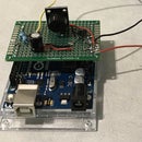
Make sure your headers are soldered onto your sensor properly and you have your wires and breadboard.
Step 2: Code Libraries
You'll want to make sure you have these downloaded.
The other libraries you'll be using, wire.h and servo.h, should be already installed by default.
Step 3: Code
Open the sketch library 'Compass' from what you just downloaded. In order to use the servo, you want to put the servo code into this code. I combined it with Hanie Kiana's code from here. The original is by Hanie Kiani, not me. It should look like this.
#include <Adafruit_LSM303DLH_Mag.h>
#include <Adafruit_Sensor.h>
#include <Wire.h>
#include <Servo.h>
#include <LSM303.h>
Adafruit_LSM303DLH_Mag_Unified mag = Adafruit_LSM303DLH_Mag_Unified(12345);
int servoPin = 3;
Servo Servo1;
void setup(void) {
  Serial.begin(9600);
   Wire.begin();
  Servo1.attach(servoPin);
  Serial.println("Magnetometer Test");
  Serial.println("");
  if (!mag.begin()) {

    Serial.println("Ooops, no LSM303 detected ... Check your wiring!");
    while (1)
      ;
  }
}

void loop(void) {
  /* Get a new sensor event */ sensors_event_t event;
  mag.getEvent(&event);

float Pi = 3.14159; // Calculate the angle of the vector y,x
  float heading = (atan2(event.magnetic.y, event.magnetic.x) * 180) / Pi;
 // Normalize to 0-360
  if (heading < 0) {
    heading = 360 + heading;
  }
  Serial.print("Compass Heading: ");
  Serial.println(heading);
  Servo1.write(180-heading);
  delay(10);
}
Step 4: Wire It Together
You want the leftmost pin- SCL- connected to the A5 data input
The one beside it- SDA- connected to the A4 port.
Ground goes to Ground.
VIN goes to the 5v port.
Step 5: Add Servo to Wiring
The ground and voltage speak for themselves, but you want the data pin to be ~3.
Step 6: Test the Code
If you move the magnetometer slowly, the servo should move with it. It likely isn't vary accurate, but it's at least working with the code, so part one is complete. It's still uncalibrated, but it works.


