Introduction: Fishing Alarm LEDs Replacement - Color Change
Hi Everyone,
In this Instructable I’m gonna show you how to replace the LEDs on a fishing alarm.
Step 1: Why to Replace the LEDs?
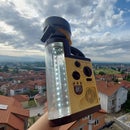
Fishing alarms are an awesome tool in your fishing arsenal. However, when you order a bunch of them at once, all of their LEDs are the same color so in situations when you have two or three one next to the other it is very difficult to know which one was triggered.
To fix this I’m gonna replace the LEDs on two of them so I can then have three different colored alarms.
Buy fishing alarms (affiliate link):
http://s.click.aliexpress.com/e/ch2rJ5B6
Step 2: Disassemble
To start, we first need to remove the screws that connect the casing. There are two screws on the top and one on the bottom. Once they are removed, we can lift up the back cover and we get access to the PCB.
Even though the two I have came in the same batch, they are slightly different. On one, the numbering on the chip is removed while on the other it is still present. However the principle of operations is the same.
Step 3: Principle of Operations
In the center part of the alarm there is rotating magnet that is actuated by the fishing line when placed on top of it. This magnet interacts with a reed switch that triggers the alarm as soon as the fish is on and starts pulling the line.
The circuit on the one with the numbering is based on the EM78P156NPJ IC chip which is an 8 bit microcontroller with 18 pins. 4 of the pins are used for the input buttons, one for the reed switch, one for the piezo speaker and two for the top LEDs. Unfortunately we cannot know the exact code that is flashed on the chip but it should be fairly simple based on the small component count.
An interesting observation in one of the alarms is the way that they managed to fix an issue directly from the factory. One of the pads where the LED is being soldered got damaged either while assembly or while manufacturing so they used a piece of wire to jump the line and connect directly to the other component. Although not the prettiest fix, it does the job well.
Step 4: Replace the LEDs
To replace the LEDs we’ll first add some fresh solder to the pads and while holding the soldering iron onto both of the LED legs, we will gently pull the LED out. When out, with a clean solder tip we can remove most of the extra solder and insert the new LED in place with the same orientation as before. The longer leg is always the positive and in my case it is being placed on the right pad on both locations.
The tricky part here is getting the length of the legs right. I used the original LEDs to solder the new ones in place at the right height and then bend the legs outward and down so they can be placed in the original holes.
Step 5: Assemble
With that, we can add the batteries back while the alarm is still open and once we confirm that everything operates as expected, we can add the back cover and the screws so we can call this project a success.
Step 6: Enjoy Fishing!
I hope that you liked this Instructable and got a better understanding of how these fishing alarms work. If you have any questions or suggestions, let me know in the comments, follow me on Instructables, and don’t forget to subscribe to my YouTube channel!
Cheers!


