Introduction: Folding Arcade Cabinet


This is a "Bartop" RetroPie arcade machine that folds up for storage. You can replace the joystick and buttons with a keyboard and trackball so it becomes a Linux desktop machine. It was mostly made with scrap wood from skips, old DIY projects, etc. The total cost was around £15 plus a Raspberry Pi (£25).
Do I want an arcade machine? Probably not. But I do want learn more about Linux and the Raspberry Pi. An arcade machine seems a good place to start. However I still get a pain in my stomach when I see a command line: it's like going back to the 70s when Dinosaurs Ruled The Earth.
Does it look good? Having spent so long building it, I'm unable to tell - but other people like it.
This Instructable will give tips on building the wooden case, how to connect the various modules and how to make the joystick detachable.
I won't explain how to install the RetroPie system into a Raspberry Pi. There are lots of Instructables and other websites explaining the process. But I will explain how to get the popular DragonRise controller to work properly - lots of people have trouble.
The whole construction can be done with handtools: drills, saws, files, sandpaper, glues, etc. Any extra power tools you have will make things easier. Making the joystick detachable is a little harder; finding a friend with a press-drill or even a lathe will help and you'll need an M4 tap. The electronics work will require a soldering iron, multimeter, cutters, odd bits of wire, etc.
I'm not trying to tell you how you should do it, just how I did it. No doubt you'll make yours your own way. Maybe I can inspire or encourage you or give you a few hints.
(Disclaimer 1: Depending on your country, removal of wood, etc. from skips left in a public place may be legal through "Abandonment of Property" laws or their removal may constitute theft; I can find no examples of anyone being successfully prosecuted, anywhere, ever. Of course, morally, recycling is good; landfill is bad.)
(Disclaimer 2: If you're making it out of MDF, wear a face mask; MDF is nasty stuff.)
(Disclaimer 3: Depending on your country, downloading a copy of a copyrighted game for which you don’t own the original media may not be legal. You can be confident that the millions of people who play games on Retropie all own copies of the original media or only use public domain games.)
Step 1: Materials

How much it costs will depend on what you have available already.
I bought the following materials new from eBay
- Raspberry Pi 3B £25
- Buttons and Joystick £10
- 12V-to-5V Buck PSU £1
- HDMI to VGA convertor £1
- PS3 to USB convertor £1
- USB hub £1
And from a car boot sale:
- 12V 2A mains PSU £0.50
- amplified speakers £0.50
- mini keyboard £1
The VGA monitor and the PS/2 trackball were free from an office clearance. I guess we all have a technology midden filled with such stuff. The paint was £2 from a "pound store".
The wood was all scrap so was free. If, unlike me, you don't hoard old pieces of wood "that might come in handy one day" then I guess you could buy some. New wood is really expensive and you might be better to take apart an old wardrobe or chest of drawers from Freecycle. 1950s and earlier furniture is generally made of good quality materials.
The sides of my case are 12mm plywood and the front/back/top/bottom are 4mm ply. You could make it all out of 13mm MDF but it would be very much heavier. As a rough guide, I used
- 12mm ply: 0.3 sq m
- 4mm ply: 0.8 sq m
- 10mm square beading: 4m
The actual dimensions will depend on your monitor. The width and height of the monitor determines the overall width and height of the case. I've included photos and drawings of my build but you will have to scale it to fit your requirements.
(The UK word "skip" does not translate to the US word "dumpster". A skip is usually open-topped and contains e.g. building or DIY waste. A Dumpster is a brand name and is usually closed and contains household garbage. Australia and NZ have yet other words. A UK "charity shop" is not quite the same as a US "thrift store". "Car boot sale" doesn't have a US equivalent; "flea market" and "yard sale" are not quite the same.)
Step 2: The Folding Mechanism


Step 3: The Front/back/top/bottom Panels


The front/back/top/bottom panels are all 4mm 3-ply. It seems a little flimsy at first but when it's been glued or screwed to the side panels it makes a stiff box. 3-ply is a lot lighter than MDF.
Measure how the monitor fits between the two side panels (after allowing for the thickness of the battens). That will give you the width of the panels for the monitor unit.
I prefer to cut 3-ply with a Stanley knife (box cutter). I find it gives a cleaner straighter edge. Just go over the cut lots of times.
Cut a hole in the monitor panel the size of the monitor screen and maybe a smaller hole fo rthe monitor controls.
The monitor panel, the "marquee" (top-front) panel and the top panel are glued in place. The back panel and the panel under the "marquee" (which holds the speakers) are screwed into the battens. Use screws, not glue, for future access. The back panel is made from two pieces which are at a slight angle to each other. Glue them to form a single piece with scrap wood overlapping the join.
Glue battens onto the top panel and marquee panel so that you can screw them onto the back panel and the panel under the marquee.
Similarly, cut panels for the front/back/top/bottom of the "keyboard unit". I glued the front, back and bottom panels onto the side panels at this point. I knew I would have to cut some holes in the back panel for connectors but it was too difficult to work out where until after I'd built the unit. Once again, glue battens in to re-inforce the corners.
The top panel of the keyboard unit is made in two pieces. The back piece is 50mm wide and is glued in place. The front part is screwed in. It can be removed to access the Raspberry Pi and other electronics and can be replaced by a keyboard and trackball.
The back part of the top panel of the keyboard unit has holes in for the cables that connect to the monitor unit. The bottom edge of the monitor unit is boxed-in with 3-ply and the cables are routed through it.
Step 4: The Joystick


The joystick has to be modified so the "keyboard unit" can fold into the "monitor unit". It's so long that otherwise it would hit the screen.
When I ordered the joystick, I thought that the 'screwhead' on the underside was really a screw that I'd be able to unscrew to remove the shaft. It isn't. It's just part of the solid joystick shaft.
So I sawed the joystick shaft into two pieces; drilled both; tapped them with an M4 thread, and glued a piece of M4 threaded rod into one half of the shaft.
The ball normally unscrews but I glued it on as the unscrewing now happens lower down.
It worked well but was hard to unscrew - the bottom part just turns. So I filed two flats on the lower half of the shaft to fit a spanner onto.
The joystick came with 8 large buttons, two smaller buttons and a USB controller. You can get them on eBay for £10 or less. I won't give a web address as they quickly go out of date. Search eBay for "arcade joystick buttons" and look for ones like those in my photo.
The joystick is quite nice and the buttons are just about OK. They have a rather light action. Better buttons are much more expensive but might be worth it.
Choose a physical layout for the buttons. There are suggestions on the web. Every gamer has their own opinions.
Step 5: The USB Controller

The USB controller is labelled "DragonRise" and is available all over the web. It seems to be the most popular one. Like the buttons, it's OK but it's not great. The latency is short but a lot of people have had problems interfacing it to RetroPie. There are lots of discussions in chatrooms and lots of conflicting and poor advice. So I'm going to go into it in slightly more detail.
I'll assume you've successfully installed RetroPie. It really is straightforward even for a Raspberry Pi noob like me. There are lots of web pages and Instructables telling you what to do. There are also lots of explanations of how to use the command-line interface to Linux (ugh!).
At the very least, learn how to use the command line to change directory (cd command), copy files (cp), move files (mv), delete files (rm), find files (find), edit text files (nano) and read a USB drive (mount). Linux might try to stop you doing something "dangerous" and tell you that you don't have permission - preface the command with 'sudo'. To get to the command line from RetroPie, hit F4. To return to RetroPie, type 'sudo reboot'. You'll need to plug a keyboard into the Raspberry Pi of course.
I happened to have a PS3 controller with a USB interface. That plugged into the Raspberry Pi and worked straight away. It's a joy to use compared with the DragonRise. Several times, I considered junking the DragonRise and soldering the buttons to the PS3 controller PCB.
But I persisted with the DragonRise. It was a good thing that the PS3 controller showed me that I was on the right lines - it gave me hints as to how the DragonRise might be persuaded to work.
In RetroPie, the game controller setup is described by "config" files - usually with the cfg extension. Part of the problem is that there are several cfg files squirrelled away in the filing system. Not all are automatically updated when you set up your controller. I'll refer to where the cfg files are located in the directories in my RetroPie setup. Yours might be slightly different depending on your RetroPie version. You can always use the "find" command to locate files.
Every button has a reference number in RetroPie; they start at 0. In addition, the joystick switches have a number - often called "axis" in cfg files - which might be called something like -1 and +1 for, e.g., the left and right axes. The two smaller pushbuttons act as "coin" or "select" or "start" or "play" or some similar meaning depending on the specific game. The other pushbuttons correspond to the 'A', 'B', 'X', 'Y', left/right 'shoulder' and left/right 'trigger' of the PS3 controller. That's what they're called even if you aren't using a PS3 controller.
- 0 Y
- 1 B
- 2 A
- 3 X
- 4 Right triggger
- 5 Left triggger
- 6 Right shoulder
- 7 Left shoulder
- 8 Select
- 9 Start
- -0 Left axis
- +0 Right axis
- -3 Up axis
- +3 Down axis
I connected the buttons to the DragonRise in the order shown. That's fairly close to the order of the PS3 and I knew the PS3 controller worked.
When RetroPie first sees a controller, it will ask you to configure it - i.e. say which button is which. That sets up some but not all of the cfg files. If you want to change the configuration, in the main RetroPie menu, press the 'Select' button then use the joystick and 'A' button to select "configure input". If you've messed things up so much that those buttons don't work then delete the file 'es_input.cfg' in the '/opt/retropie/configs/all/emulationstation' directory. When you reboot, you'll be asked to configure the controller.
As you run the controller-configuration program, it will tell you the numbers of the buttons you've chosen. Make a note of them.
In RetroPie, games are called "ROMs". Each game is executed by an emulator which reads the ROM file. You have to match the right emulator to each ROM. So an emulator corresponds with the original hardware the ROM ran on. You might find several ROMs for a particular game some of which don't work. You might find several emulators some of which don't work. You have to mix and match. (Many ROMs are copyrighted. In many countries, to remain legal, you should only download ROMs for games for which you own an original copy.) Roms are located in
/home/pi/RetroPie/roms
ROMs for particular hardware should be together in a sub-directory with a name that tells you what hardware they run on. In RetroPie that's called a "system". There will be a corresponding emulators.cfg file for that sub-directory that says what emulators might work. You'll find emulators.cfg files in /opt/retropie/configs/ If you press Tab while a game is loading, you will be given a list of emulators to choose from - it's the list in the emulators.cfg file. Other files for a "system" are scattered around in half a dozen different directories. It's a mess.
So there will be a cfg file that says the default buttons for all games and each game can have its own cfg file. Don't set up individual cfg files until you've got everything else working.
Button configuration files can be found in /opt/retropie/configs/all and the sub-directories off it.
Use the nano editor to look at all the cfg files and see what's in them. You should see the names of buttons and their corresponding numbers.
Having got this far, you've probably got the DragonRise controller working with the RetroPie main menu. But it won't work in games - or it won't work properly in some games.
Look in the directory
/opt/retropie/configs/all/emulationstation
and edit the file
es_input.cfg
You'll see that it refers to "DragonRise Inc. Generic USB Joystick ". We need a config file with that name.
"DragonRise Inc. Generic USB Joystick .cfg"
Note the number of spaces. Here I've replaced space with '*' but don't type '*' - that's just the number of spaces you need.
"DragonRise*Inc.***Generic***USB**Joystick**.cfg"
Download the "DragonRise Inc. Generic USB Joystick .cfg" file from this Instructable. and copy it into the directory
/opt/retropie/configs/all/retroarch/autoconfig
Edit the file using nano. Check that the button and "axes" numbers are what you've used.
(Note that the Linux command line doesn't like filenames with spaces. You have to enclose them in double quotes in any command line.)
Also in
/opt/retropie/configs/all/emulationstation
is
es_input.cfg
which lists the button numbers. Make sure they match what you used.
Finally, each game might have its own config file and that file might not use the name or format that is "standard" in RetroPie.
For instance, many people can't get the Metal Slug emulator to work. It uses a config file called /opt/retropie/emulators/pifba/fba2x.cfg or /opt/retropie/configs/fba/fba2x.cfg
In that file is a list of button assignments but it's in a different format from other cfg files. So, for instance, the joystick should defined by
#Joystick axis JA_LR_1=0 JA_UD_1=3
(the "_1" was originally not in the file but is needed and the "3" originally had the wrong value).
To conclude, the RetroPie system is a complete mess. It's written by geeks for geeks. There's an enormous amount of work gone into it - thanks guys - but it can be a real struggle. You'll find lots of people in chat rooms tearing their hair out and begging for help.

Step 6: Wiring It Up


I started with the electronics laid out on the bench then, when it was working, screwed it to a board and then screwed the board into the "keyboard unit" of the cabinet.
The buttons, joystick and DragonRise controller are mounted on a sheet of 3-ply. I drilled the holes with a "stepped drill" (£1 from eBay) - a good investment. The 3-ply is screwed into the keyboard unit.
The whole thing is powered from a 12V switch-mode PSU "swinging brick" - probably from a laptop. My monitor required 12V at 1A - check what yours wants.
The PSU is screwed down right up against the back panel of the keyboard unit. A hole is cut the the panel so that a mains plug ("kettle lead") goes straight into the PSU. I then found I needed a mains on/off switch. You occasionally find "swinging brick" PSUs with a switch but, in this case, I added an inline switch in the "kettle lead".
I cut into the 12V cable to attach two short wires that go into a screw connector terminal block. On the other side of the terminal block is a 12V-to-5V buck convertor. It's quite a small convertor but can supply 1A without getting hot. (Use a buck convertor, don't use a 7805 regulator - it will overheat.) Search eBay for "12V 5V buck" and look for a photo of one like mine; others exist but I know that one works well; I've had others that get hot.
The Raspberry Pi is powered with 5V via a micro-USB connector. I just cut a micro-USB lead in half and connected it to the terminal block (red +5V; black 0V).
The old monitor I'd chosen has a VGA input. The Raspberry Pi produces HDMI. So I bought a convertor on eBay. It works just fine. If you're buying a modern monitor then it will probably have an HDMI input already but old monitors in charity shops and car-boot sales are often VGA. "Dead" monitors can be free and often just need the power capacitors replaced. There are explanations on the web. If you can get a "dead" laptop for free, you could try converting its screen into a monitor.
I glued a USB hub inside the back of the keyboard unit and connected it to the Raspberry Pi. That way I could easily plug in a keyboard and mouse. I did the same with a double-ended RJ45 "through coupler" for ethernet.
A Reset button is very useful when you're setting-up RetroPie. I wanted one on the back panel of the keyboard unit but couldn't find one that was sufficiently low-profile. In the end I hot-glued a tactile button to the back panel so that a little of it protrudes. There are lots of web pages describing which pins to connect the reset button to; it varies according to the version of Raspberry Pi.
Step 7: The Speakers


The speakers are from a car boot sale for £0.50. Charity shops are also good sources. Choose stereo speakers with an amplifier. If the amplifier is powered from 12V (i.e. the same as the monitor) then you can run it straight from the PSU.
My amplifier/speakers had an unmarked power socket. I don't know what voltage they needed but they worked OK at 12V with a bit of mains hum. Maybe they really wanted 9V. I put an 8ohm 1W resistor in the 12V lead going to the amplifier which eliminated the hum. That's not what you're meant to do with an amplifier power supply but it works fine and sounds good. You're not expecting hi-fi - it's just for the beeps and explosions of games.
The amplifier and speakers are glued onto the panel under the "marquee" so I ran cables for the audio signal and the 12V up beside the screen. It might make sense to put the amplifier in the keyboard unit with the rest of the electronics but then you have to work out where to put the volume control.
In my case, the amplifier has stereo slider-pot volume, treble and base controls. They're all on a small panel so, rather than finding stereo potentiometers, I just cut a square hole and glued the panel behind it.
The the amplifier has a 3.5mm stereo jack socket and so does the Raspberry Pi. Cables which connect them are very common - you've probably got one spare.
Step 8: Decorating the Cabinet

The cabinet is painted with oil-based gloss black and red. Some of the components use cellulose-based spray paint. Don't spray cellulose paint on top of new-ish gloss paint - it goes crinkly. I'm not happy with the surface finish of the oil-based paint; I'd recommend mostly spray-paint with oil-based just for the red edges.
Having spent so little making the arcade machine, I was appalled to find how much vinyl stickers cost. I'd have to spend more on stickers than on the whole of the rest of the build.
A good compromise is to get glossy photos printed. 7x5" photos cost under £0.30 and have rich colours if you choose the right high-street shop.
The "ARCADE" letters along the top are 50mm high and were printed as a 6x4" glossy photo.
I spent a while designing a sticker-bomb effect then decided I didn't like it. The mock-ups above show sticker-bomb on the lower part of the sides. It would be produced by printing just two 7x5" photos for each side. The "Asteroids" graphics mock-up can be produced by cutting 1mm wide white paper strips then sticking them on with PVA and varnishing. I think it's a nicer effect than the sticker-bomb. But the plain black and red looks good. I haven't decided yet.
Step 9: A Keyboard and Trackball


As I said, I'm not sure I really need an arcade machine so I decided it should double as a desktop computer. You can unscrew the arcade joystick and buttons panel and screw in a panel with a keyboard and trackball.
A full-sized keyboard is too big to fit in the "keyboard unit" but I spotted a mini USB keyboard at the car boot sale for £1. They're a fairly common accessory for tablets. It's a bit small but the keys are a useable size. It came in a faux-leather "wallet" which I removed. The resulting panel fitted nicely behind 3mm hardboard. It plugs straight into the Pi.
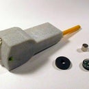
The trackball is an ancient Logitech Trackman Marble Trackball and had a PS/2 connector. I got a PS/2-to-USB convertor on eBay - buy one that looks like my photo. Some people report problems with that model on a PC but it works fine with a Raspberry Pi. I only tried the mouse connector; I could try the keyboard connector if anyone is interested but USB keyboards are extremely cheap.
A little sawing and hot-glueing fixed it behind the hardboard panel. I used the original mouse buttons but fitted tactile-switch key-caps left over from a previous project. You could just use tactile-switches.
Step 10: Conclusion


It looks good. Or at least I think it looks good - I can no longer tell. Everyone who sees it is enthusiastic or perhaps they're being polite.
It achieves what I wanted. It behaves like either an arcade machine or a desktop computer. It folds away for storage. And it cost very little to build. Other people spend hundreds of pounds building arcade machines and no doubt those machines look better but you don't have to spend that much. Charity shops, car boot sales, skips and your own technology midden will provide most of what you need.


