Introduction: Frank_One


It’s alive, It’s moving, it’s alive, it’s alive, IT’S ALIVE!
Hit off Halloween with a classic, inspired by Mary Shelly’s creature, Frank_One is a fun and interactive project for this occasion. Much like the game Operation, the creature is lying on an operating table where a few of its organs and some elements in the table enable interactions that might surprise you! The more you tweak with the creature, it’s life starts depleting, until there is no more light left in his life bar.
Supplies
- Arduino Uno Board
Description: Microcontroller board compatible with arduino coding.
Qtv. : 1
2.Servo Motor
Description: Rotary actuator or linear actuator that allows for precise control of angular or linear position, velocity and acceleration.
Qtv. : 1
3.Photoresistor
Description: Light-controlled variable resistor. The resistance of a photoresistor decreases with increasing incident light intensity
Qtv. : 1
4.Potentiometer
Description: A potentiometer is a three-terminal resistor with a sliding or rotating contact that forms an adjustable voltage divider.
Qtv. : 1
5.Buttons
Description: Buttons communicate actions that users can take. They work as an input.
Qtv. : 2
6.LED
Description: light-emitting diode (LED) is a semiconductor device that emits light when an electric current is passed through it.
Qtv. : 4
Ref.
7.10 Segment LED Bar
Description: A 10 segment LED bar graph is basically 10 individual LEDs in a package that looks and can function like a bar graph.
Qtv. : 1
8.Resistors 10 OHM
Description: A resistor is a passive two-terminal electrical component that implements electrical resistance as a circuit element.
Qtv. : 9
9.Resistors 220 ohm
Description: A resistor is a passive two-terminal electrical component that implements electrical resistance as a circuit element.
Qtv. : 4
10.Resistors 100 ohm
Description: A resistor is a passive two-terminal electrical component that implements electrical resistance as a circuit element.
Qtv. : 5
11.Battery Snap-on Connector Clip
Description: Snap-on Connector clip for batteries, connects directly with the arduino board.
Qtv. : 1
12.9V Battery
Description: Device consisting of one or more electrochemical cells with external connections provided to power electrical devices. 9V of energy.
Qtv. : 1
13.Wire
Description: Facilitates connection between components and the arduino board.
Qtv. : -
14.Bakelite welding plate
Description: Welding plate used to create the board with all it´s components and circuits.
Qtv. : 1
Step 1: Draw or Download Frank_one´s Parts
You can find the drawing of this model in the following dwg. file. It has been arranged to be cut in 3 a4 MMA boards.
Attachments

Step 2: Laser Cut Frank_one

For this project he have used A4 3mm (MMA) boards in the following colors :
Black, white and green. To achieve the red and metal color in the heart and bone without utilizing more boards, we have used spray paint.
Step 3: Frank_one Assemble


Utilizing MMA glue, build the bead and individual parts of the body. Such as : The abdomen, pants, feet, and head. This will make the assembly easier with the components.
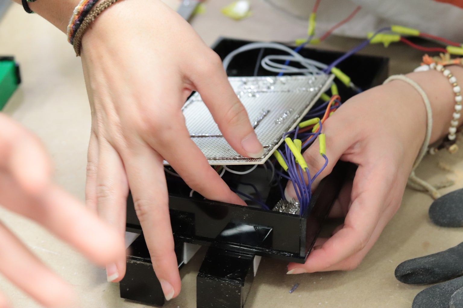
Step 4: Weldging the Circuit Board Following the Circuit Diagram


Utilizing the circuit diagram we have provided, weld the components into the board. It should look like the image.
Step 5: Assemble Frank_one Fully


Time to assemble ! now you have become the creatures creator! Be very vigilant, bringing Frank_one to life is no easy process. We recommend starting from the bottom-up. Starting with the 10 segment led bar, potentiometer and photoresistor. The heart buttons is where it gets tricky, be sure to stabilize the columns that will connect the buttons with the red heart before blueing the abdomen to the bed. For the servo we have glued an axis that will be later blued to the back of Frank's head (as shown in the photograph).
Step 6: Coding : Arduino
/*
HALLOWEEN. FRANKENSTEIN PROJECT 1 GRUP 101ANDREA BAEZ MARTA TUDURÍ NOEMÍ VIVES */
#include
Servo myservo; // create servo object to control a servo
int angle1 = 90; //Define and intialize variable angle 1 (HEAD) int angle2 = 30; //Define and intialize variable angle 2 (HEAD) int angle3 = 150; //Define and intialize variable angle 3 (HEAD) int corazonizquierda = 2; //Define and intialize pin for left heart button int corazonderecha = 3; //Define and intialize pin for right heart button int PWM = A5; //Define and intialize pin for potentiometer int ledPin = A4; // Define and intialize pin for blue led int ledPin2 = A3; //Definir y inicializar pin Led AZUL 2 int ledR = 4; // Define and intialize pin for left eye (red led) int led2R = 5; //Define and intialize pin for right eye (red led) int Resistor = A2; // Photoresistor at Arduino analog pin A0 int v1 = 7; // Define and intialize pin led 1-2(Segment led bar) int v2 = 8; // Define and intialize pin led 3-4 (Segment led bar) int v3 = 10; // Define and intialize pin led 5-6 (Segment led bar) int v4 = 11; // Define and intialize pin led7-8 (Segment led bar) int v5 = 12; // Define and intialize pin led 9-10(Segment led bar) int contador = 0; //Define and intialize life counter
int buttonStateA; //Initialize and declare each button state for every button.(corazón izquiera y corazón derecha) int buttonStateB;
int lastButtonStateA;//Initialize and declare each button state for every button.(corazón izquiera y corazón derecha) int lastButtonStateB;
void setup() { myservo.attach(9); // Attaches the servo on pin 9 to the servo object
lastButtonStateA = 0; lastButtonStateB = 0;
pinMode(corazonizquierda, INPUT); //Define state for pin button, left heart pinMode(corazonderecha, INPUT); //Define state for pin button, right heart pinMode(ledR, OUTPUT); //Define led state for left eye pin pinMode(led2R, OUTPUT); //Define led state for right eye pin pinMode(ledPin, OUTPUT); //Define led state for blue led 1 pinMode(ledPin2, OUTPUT); //Define led state for blue led 1 pinMode(PWM, INPUT); //Define state for potentiometer pin pinMode(Resistor, INPUT); //Define state Photoresistor pin pinMode(v1, OUTPUT); //Define state for pin Led 1-2 (Segment led bar) pinMode(v2, OUTPUT);//Define state for pin Led 3-4 (Segment led bar) pinMode(v3, OUTPUT);//Define state for pin Led 5-6 (Segment led bar) pinMode(v4, OUTPUT);//Define state for pin Led 7-8 (Segment led bar) pinMode(v5, OUTPUT);//Define state for pin Led 9-10 (Segment led bar)
}
void loop() {
//Configuration for potentiometer ( blue bed leds )
int valor = analogRead(PWM); //Define and initialize int value for potentiometer valor = map(valor, 0, 1023, 0, 255); //Convertion values for potentiometer in led intensity values. analogWrite(ledPin, valor); analogWrite(ledPin2, valor);
// Buttons and servo conficugration
buttonStateA = digitalRead(corazonizquierda); buttonStateB = digitalRead(corazonderecha);
if ( buttonStateA == LOW && buttonStateB == LOW) { //When none of the buttons are pressed, angle1 of the servo myservo.write(angle1); delay(100); digitalWrite(ledR, LOW); //Red eye leds are off digitalWrite(led2R, LOW);
}
else if ( buttonStateA == HIGH && buttonStateB == HIGH) { //When both heart buttons are pressed, the head moves and the eyes are lit. myservo.write(angle2); delay(300); myservo.write(angle3); delay(300); digitalWrite(ledR, HIGH); //Red led eyes are lit digitalWrite(led2R, HIGH); }
if ( buttonStateA == HIGH) { //If just the left heart button is pressed, the head moves to angle2 myservo.write(angle2); delay(100);
if (buttonStateA != lastButtonStateA ) { //Condition if the buttonState is different than the last button state. contador++; //Count every time there´s a change from 1 to 0 lastButtonStateA = buttonStateA; // The last button state and the button state is the same, until the button is pressed.
}
} else { lastButtonStateA = buttonStateA; //The button state 0 is now 1 }
if ( buttonStateB == HIGH) { //If just the right heart button is pressed, the head moves to angle3 myservo.write(angle3); delay(100);
if (buttonStateB != lastButtonStateB ) { //Condition if the buttonState is different than the last button state. contador++; //Count every time there´s a change from 1 to 0 lastButtonStateB = buttonStateB; // The last button state and the button state is the same, until the button is pressed.
}
}
else { lastButtonStateB = buttonStateB; //The button state 0 is now 1 }
// 10 SEGMENT LEDS CONFIGURATION
digitalWrite(v1, HIGH); digitalWrite(v2, HIGH); digitalWrite(v3, HIGH); digitalWrite(v4, HIGH); digitalWrite(v5, HIGH);
if (contador > 3) { digitalWrite(v5, LOW); }
if (contador > 5) { digitalWrite(v4, LOW); }
if (contador > 7) { digitalWrite(v3, LOW); }
if (contador > 8) { digitalWrite(v2, LOW); } if (contador > 10) { digitalWrite(v1 , LOW); }
//CONFIGURACIÓN PHOTORESISTOR
int value1 = analogRead(Resistor);
if (value1 > 10) { digitalWrite(ledR, HIGH); //leds rojos de los ojos encendidos digitalWrite(led2R, HIGH); }
else { digitalWrite(ledR, LOW); //leds rojos de los ojos apagados digitalWrite(led2R, LOW); }
}
Step 7: Now You Are Ready to Go !


Congratulations you have become a creator !
Happy Halloween !

Participated in the
Halloween Contest 2019


