

Introduction: Getting Started - Navigation and Menus


The following information is a single lesson in a larger Tinkercad project. Check out this and more projects on Tinkercad.
Project Overview:
Welcome to the world of design!
Design is the art of discovering all the things that haven't been made yet. It is equal parts learning and teaching, breaking and making, seeing and showing.
Design is sharing!
Tinkercad is an amazingly powerful easy-to-use tool for creating digital designs that are ready to be 3D printed into super-cool physical objects. You will be guided through the 3D design process via easy hands-on "Lessons", that teach you the basics of Tinkercad before moving on to more complex modeling techniques.
Let's get started!
Step 1: Welcome!
Welcome to Tinkercad!
Tinkercad is a fun and easy-to-use tool for creating digital designs that are ready to be 3D printed into physical objects. In this project, we will provide you with the foundational skills necessary to start designing amazing models.
In your first lesson, you will be guided, step-by-step, through how to use the Workplane, Tinkercad's menus and interface, camera controls, and the basics of moving objects. Let's go!
Instructions
- Continue to the next step.
Step 2: Arriving in Tinkercad

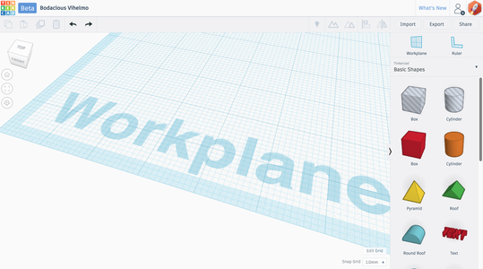
When you first arrive in Tinkercad, you will see the Workplane, which looks like a blank sheet of graph paper. This is where you will be creating your designs.
Now find the Tinkercad logo, in the upper left. Below the logo is the menu bar which extends across the top of the screen. The buttons across the menu bar are actions that you can perform with Tinkercad.
To the left of the Workplane, under the Tinkercad logo, are the Viewcube and navigation buttons.
To the right of the Workplane is the Shapes menu. These shapes are the foundation of all creation in Tinkercad.
Now, let's take a detailed look at the Workplane.
Instructions
- Continue to the next step.
Step 3: Exploring the Workplane

The Workplane is the surface upon which all things you create will appear; it is designed to help you accurately position shapes.
The workplane looks like a piece of graph paper. It is broken up in to 1 centimeter (cm) "major grid lines" (the thick blue lines) and 1 millimeter (mm) "minor grid lines" (the thin blue lines).
In the lower right-hand corner, the Edit grid button allows you to change the units of your design. You can change the grid to measure with major grid lines in inches and minor grid lines in eighths of an inch.
Instructions
- Continue to the next step.
Step 4: The Viewcube

Your view in Tinkercad is called the camera. In fact, the terms we are going to use are movie camera terms: tilt, rotate, pan, and zoom!
The first method of moving around Tinkercad is the viewcube, which is linked to your view of the 3D design and Workplane, and helps you tilt and rotate your camera.
Instructions
- As you hover your cursor over the Viewcube different areas will highlight.
- Clicking on any of the highlighted area of the Viewcube will rotate the camera to that view.
- As the Viewcube is moved the shapes on the workplane will also be rotated to match.
- Go ahead and click different areas of the Viewcube to see the results in the editor window. You should see your view of the Workplane, and any shapes on the Workplane, rotating with the Viewcube.
- Want to move your camera back to where you started? Click the home button below the Viewcube to return to your starting view. Now you're getting it!!
Step 5: What Are Hints?

See the orange shapes in the middle of the Workplane? Those are called Hints.
Hints are outlines of shapes or workplanes to guide you through the lessons.
Instructions
- Continue to the next step.
Step 6: Shapes Menu

The hint wants you to grab a cube and place it in the center of the Workplane.
To do that, we'll need to explore the Shapes menu.
Instructions
- Find the Basic Shapes menu and drag a box to the workplane and place it within the Hint.
- Continue to the next step.
Step 7: Viewing Your Object From All Sides

Rotate around your shape and check to see if it is completely within the hint.
If you find that your block is not perfectly placed (like the image below), it's OK, simply click and drag the shape until you are happy with its placement.
Still not sure you've got it right? Let's take a closer look by zooming in.
Instructions
- Double check your box placement within the Hint by rotating around it and looking at it from all sides.
- Continue to the next step.
Step 8: Zooming in on Your Object

If you need to zoom in on your object, you can use your mouse scroll wheel or touch pad.
Try it!
Instructions
- If you have a mouse with a scroll wheel, use it for zooming in and out.
- If you use a touchpad, you will zoom using the gesture that you normally use in other apps when wanting to zoom.
- Continue to the next step.
Step 9: Controlling the Camera With Your Mouse

There are three main ways to move effectively in your 3D design: Rotate, Pan, and Zoom.
If you move your mouse-pointer over the Workplane and right click drag (press and hold right button + move your mouse), you'll notice that your camera will rotate and tilt.
To pan, hold down Shift and right click the Workplane. You'll see that your view moves in a straight line (linear), as opposed to rotational fashion.
Tip: You can also pan by holding the mouse wheel and dragging.
If you have a scroll-wheel on your mouse, you can use it to zoom in and out.
Instructions
- Move your mouse-pointer over the Workplane, then click and hold your right mouse button to rotate and tilt your camera.
- While holding Shift, move your mouse-pointer over the Workplane, then click and hold your right mouse button to pan your camera right and left.
- Continue to the next step.
- Stuck?
HINT:
If you have a trackpad, you will have to experiment with how you use it to navigate Tinkercad; not all trackpads work the same.
Step 10: Using the Shape Window

When an object is selected, you will see the Shape window located in the upper right corner of the Workplane.
The Shape window gives you control over a number of properties of an object, including the color, visibility, transparency, and hole functions.
Instructions
- Click on the Shape window, and select Color. Click around on different colors, and see how your object changes.
- Continue to the next step.
Step 11: Working With Shapes in 3D Space

We're now going to explore working with objects in 3D space, which means not just moving them on the Workplane, but also moving them away from and even underneath the Workplane.
This can be tricky, at first, so let's learn some tools to help us think in 3D.
For the rest of the lesson, we'll need a second object so we can explore these tools.
Instructions
- Drag a sphere to the workplane and place it within the sphere hint.
- Continue to the next step
Step 12: The 3D Modeler's Salute!

Our first tool is the 3D Modeler's Salute, which will help you think in 3D!
Make your hand like the hand in the picture. We're going to give each finger a letter:
Instructions
- Your middle finger will be the X axis, which travels from left to right, defining the bottom edge of the Workplane.
- Your index finger will be the Y axis, which extends from the bottom of the screen to the top, defining the left edge of the Workplane.
- Your thumb will be the Z axis, which is an invisible edge that is perpendicular to the Workplane.
- These axes meet at the Origin, the corner of the grid with the word "Workplane."
- Continue to the next step.
Step 13: Translation, More Than a Fancy Word for Moving!

In 3D modeling, there are many ways to move an object.
The first type of moving is "translation." Translation is changing an object's position without rotating the object or changing its size.
When you move an object from left to right on the Workplane, you are translating it in the positive direction along the X axis. When you move an object from near to far, you are translating it in the positive direction along the Y axis.
When you lift something off the Workplane, you are translating the object in the positive direction along the Z axis.
Let's move things in Tinkercad to see what this means.
Instructions
- Try the 3D Modeler's Salute!
- Continue to the next step.
Step 14: Translating Objects Along the Z Axis

Notice the arrow handle above the sphere. This handle allows you to move an object up or down.
You'll also notice the sphere leaves a shadow on the Workplane. When you drag it up, the distance between the shadow and the sphere increases, and a number measurement appears to the right of the sphere. This number, and the corresponding lines, indicate the distance between the object and Workplane.
Instructions
- Click on the sphere.
- Use the vertical drag handle to move the sphere to 11mm off the Workplane.
- Continue to the next step.
Step 15: Translating Objects Along the X and Y Axes

To move an object along the X and Y axes, simply click and drag the object.
As you do this, you will see two numbers appear to the right of the object. These numbers represent the distance an object has been moved from its previous position.
Instructions
- Drag the sphere 30mm so that it sits on top of the cube, intersecting as shown.
- Continue to the next step.
Step 16: The Hole Property

Now, we're going to introduce two Boolean operations; addition and subtraction. A Boolean operation is how you can combine two objects into a new shape.
Boolean addition adds one shape to another, so if the box and the sphere were combined, you'd have a single shape that was a box with a hemisphere protrusion on top.
With Boolean subtraction, you can turn one shape into a negative space, and use it to remove material from another! In this case, you'd be left with a box that has a hemisphere hole on top.
Let's try a Boolean subtraction!
Instructions
- While the sphere is selected, click "Hole" from within the Inspector.
- Continue to the next step.
Step 17: Selecting Multiple Shapes

In order to use the sphere to cut into the box, we need to make sure the two objects are selected.
To select both objects, we're going to use the "Band Selection" tool.
A band is a box we draw around the shapes we wish to select. Click on the empty space (not on an object, or you may drag it) to the left and above the shapes you wish to select. Then, while holding the mouse button down, drag your mouse cursor below and to the right.
Instructions
- Click and hold the left mouse button while your cursor is in empty space, outside of the shapes you wish to select, to start a band.
- Pull the band around to the objects to the opposite extreme corner.
- Let go of the mouse button.
- Continue to the next step.
Step 18: Making Complex Shapes With Grouping

By using the Group function we can use any combination of Boolean addition and subtraction to turn objects into one complex shape.
This means any combination of solids and holes can be used to make any shape imaginable!
Try that now.
Instructions
- With both objects selected, click the Group icon in the menu bar.
- Rotate around the object using the Navigation wheel or your mouse and take a look at how the shapes have changed.
- Continue to the next step.
Step 19: Congratulations!
Great job!! You've made it through your first Tinkercad lesson. We've covered a lot of material:
* Axes
* Workplane/Grid
* Navigation
* Grouping
* Shapes
* Inspector
* Hints
* Selection
* Handles
Now that you know the basics, let's move on to new topics.
Instructions
- Continue to the next lesson.
In the next lesson you will learn to navigate the user interface!
Next Lesson:Testing Your New Navigation Skills


