Introduction: HANDHELD MINI PINBALL MACHINE
MINBALL is a small scale, handheld, pinball machine that lets you experience the fun of classic arcade pinball anytime, anywhere. I made this project to practice my engineering and CAD skills and share it with the rest of the internet.
This instructable covers my design and build process to create this machine, and provides resources for you to build your own.
Supplies
For my MINBALL design, I had the major custom components laser cut from 5052 H32 aluminum. However this could be realistically be substituted for a multitude of materials. (Wood, Cardboard, Paper, etc)
Supplies I Used:
- Acrylic top plate
- Aluminum side plate
- Aluminum mid plate
- Aluminum bottom plate
- Aluminum ball launcher
- PLA left flipper
- PLA right flipper
- M3 10mm bolts (x19)
- M3 14mm bolts (x4)
- M3 nuts (x27)
- M3 washers (x4)
- Rubber O-rings (x3)
- Pen spring
Tools I Used:
- Electric screwdriver
Software I used:
- Fusion 360
*Supplies & tools may change between different MINBALL variations. You may want to outsource your laser cutting if you don't have your own tools to do so.
Step 1: BASIC IDEA
This step includes creating a simple idea for your machine, focusing on the main goal you want it to achieve without worrying about the specific details/mechanisms.
My goal was to create something portable that could be comfortably held in both hands. So I chose a frame size which is roughly the size of a large smartphone. This means most people would already be accustomed to holding a similar object making it more intuitive to use.
As for game play I knew I wanted the classic double flipper pinball design. I wanted it to reflect the classic pinball style with a modern twist.
Also I knew I wanted it to be simple in every way possible. Making it easy to use, assemble, and modify were core aspects of the project.
Step 2: GENERAL DESIGN
MINBALLhas the dimensions of 3" by 5.5" by 0.75", and is assembled as a sandwich of 3-4 plates. This makes the design and build process exponentially easier as elements can be designed layer by layer and assembled with nuts & bolts through the whole assembly.
A majority of the plates are made from aluminum for strength and presentability. I originally planned to have them powder coated for visual interest but time constraints didn't allow.
The top plate is made from acrylic to allow a clear view of gameplay and to act as barrier to prevent the ball from falling out.
Both flippers are 3D printed as it is cheap, allows for design flexibility, and is visually appealing.
Bolts make up all of the pins on the board as they are rigid, can be easily removed, and are available for very low cost.
I have provided the STEP file for the whole assembly:
Attachments
Step 3: BOTTOM & MID PLATE
The bottom & mid plate is where most of the customization takes place. Holes for bolts and captive nuts in the bottom and mid plate determine the position of the pins on the board. I attempted to take inspiration from new and old pinball machines for my pin pattern but it is highly recommended that you experiment with your own when attempting to recreate this project.
However 4 holes in the corners and 2 pins toward the bottom are highly recommended as they keep the assembly together and create pivot points for both flippers respectively. Along with 1 pin at the bottom that acts as a stop for the ball launcher spring.
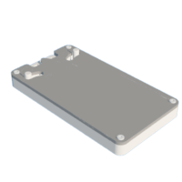
The bottom plate is made from 0.063" 5052 H32 Aluminum.
The mid plate is made from 0.100" 5052 H32 Aluminum.
Step 4: SIDE PLATE
This component makes up all of the side walls and sections off areas for different mechanisms. However the form of this plate could be easily modified to be used as a game obstacle. I chose to keep the sides relatively simple to ensure the ball doesn't get stuck in any unexpected places.
It is important to make sure that your side plate is taller than your ball so it will have clearance.
The side plate is made from 0.250" 5052 H32 Aluminum.
Step 5: BALL LAUNCHER
This small ball launcher has a unique design wherein a captive spring is held in the middle of the assembly. When pulled back the spring compresses against another M3 bolt. And when released it propels the ball back into play. There is a small concave at the top to center the ball. Also portions of the bottom, mid, side, and top plate have been removed to make room to grip the back of the launcher.
The ball launcher is made from 0.250" 5052 H32 Aluminum (Slightly sanded down to have clearance between mid & top plate).
Step 6: FLIPPERS
Both flippers have a distinct "L" shape and act as levers that can launch the ball upwards when flipped. They pivot around two M3 bolts and are limited in rotation by both the side & top plate. A small knob is extruded from both flippers to be interfaced with by a player's thumbs. The use of 3D printing means there is a high ceiling of customization.
The flippers are made from PLA 20% infill.
*Flippers are currently not pictured in any real photos as they were not done by submission time.
Step 7: TOP PLATE
The top plate is relatively simple. It should be translucent for easy viewing of gameplay but thickness and color are not important. The few things you have to take into account are slots for the knobs on the flippers and bolt holes in all four corners.
The top plate is made from 0.118" acrylic.
Step 8: ASSEMBLY
The assembly process is relatively simple:
Start by aligning the mid and bottom plate and inserting M3 nuts and bolts into every hole besides the ones in the far corners.
Then choose four bolts (preferably towards the outside of the board) to put four M3 washer and nuts on in order to secure the mid plate.
Next you can optionally take any rubber O-rings and wrap them around bolts of your choice.
Then place the ball launcher in its respective area and insert a small pen spring into its center slot (It should be compressed between the top of the center slot and the M3 bolt at the bottom).
Next slide the flippers onto the M3 bolts on the sides.
Also remember to put your steel ball bearing inside before closing everything off.
Finally align the side and top plate with the rest of the assembly and use four M3 nuts and bolts to fasten all the plates together via the far corner holes.
Step 9: YOU'RE DONE
Now your MINBALL machine is ready to play! You can slightly prop it up on a desk or hold it in your hands, whichever you find to be most efficient. Remember that this machine can be constructed in a multitude of ways and different renditions may look vastly different. Either way you're ready to have the classic pinball experience now with a modern twist.
Have Fun!

Participated in the
Arcade Student Design Challenge


