Introduction: Hack a Picnic Cooler (into a Thermostatic Chamber)


My colleague David and I need to soak our scintillation detectors at known constant temperatures if we are ever to graduate. Our thesis advisers need their lagers at 6 to 9 degrees Celsius, ales at 7 to 11 degrees Celsius and the occasional stout at 13 degrees Celsius.
This is what I came up with. Enjoy!
Martina
This is what I came up with. Enjoy!
Martina
Step 1: The Task

The lab already had a picnic cooler, supposedly for climate-testing of the radiation detectors (?!). The cooler came equipped with a Peltier pump that can run off AC mains or 12V DC and can either heat or cool (depending on the switch setting) the box interior. Unfortunately, there is no thermostatic control built in, so the internal temperature either approaches approximately the ambient temperature less 20 degree Celsius or heats up to +50 Celsius and stays there (probably limited electronically).
This simply screams for some micro-controller driven decision making.
Aside from a picnic cooler, the final bill od materials consisted of:
This simply screams for some micro-controller driven decision making.
Aside from a picnic cooler, the final bill od materials consisted of:
- an arduino board
(we used a pro mini 328/5V/16M, simply because they are the cheapest Arduino clone on eBay @ $2.83), - 2 relays (5V/1ch relay modules from eBay at $0.99 each),
- 2 momentary push-buttons (stolen from colleague Klemen)
[Klemen comments: "Borrowed not stolen. One day I will have them back."], - an electronics thermometer (we used a DS18B20, eBay @ $1.04),
- 5 resistors (see schematics, later on),
- an LCD 2x16 display module (HD44780 compatible module, eBay @ $2.26),
- a 7805 voltage regulator (eBay @ $0.90) and its two decoupling capacitors,
- an electrical enclosure box from the hardware store ($6.00 for the cheapest one!),
- many, many, many... wires (depths of supervisor's drawer).
Step 2: Reverse Engineering & the Hack


The chamber cover is where all the action is. After removing the black foam "rope" (that runs the perimeter of the cover and acts to seal against air drafts) and unscrewing a zillion screws underneath, the two plastic clams fall open to expose a large piece of styrofoam and all the electronics.
Our target is the underside guts of the COOL-OFF-HEAT selector switch. If you can switch between these three states by hand, it should be possible to bypass it with a handful of relays, right?
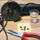
Four wide copper traces lead to the three-state switch. Two of them eihave 12V DC between them, regardless of the switch position. The remaining two are both "cold" when the switch is in the OFF position, and become energized with 12V between them for both the COOL and HEAT switch positions, but with opposite polarities for the two cases. Lookin' good! So the switch literally selects the current flow direction through the Peltier element, in turn making it pump heat ther in or out. All we need to do is cut off the connections from the switch and route them out using four thick (several amperes of current!) wires to where we will attach the relays.
Our target is the underside guts of the COOL-OFF-HEAT selector switch. If you can switch between these three states by hand, it should be possible to bypass it with a handful of relays, right?
Four wide copper traces lead to the three-state switch. Two of them eihave 12V DC between them, regardless of the switch position. The remaining two are both "cold" when the switch is in the OFF position, and become energized with 12V between them for both the COOL and HEAT switch positions, but with opposite polarities for the two cases. Lookin' good! So the switch literally selects the current flow direction through the Peltier element, in turn making it pump heat ther in or out. All we need to do is cut off the connections from the switch and route them out using four thick (several amperes of current!) wires to where we will attach the relays.
Step 3: All of the Toppings


Separately, the controller part needed to be developed.
User interface first.
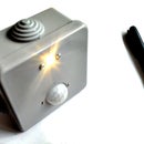
We decided that we want two buttons and a display. The display would show the desired target temperature, the actual temperature and the heat pump state (i.e. Off, COOL, or HEAT). User input would be via two momentary push-buttons. One of them would increase the target temperature by a small amount, say a tenth of a degree, each time it is pressed, and the other one would decrease it in the same sense with each press.
Thermometer
There's nothing like the simplicity and robustness of a DS18B20. I hope they gave that Dallas guy a good pat on the back when he invented it. The connection, including the 4k7 pullup, is as shown on the schematics.
LCD connections.
Switching.
Power.
The four wires that got routed out from the chamber guts in the previous step will provide a free 12V supply for the Arduino board if connected at the RAW pin. The on-board regulator will provide 5V power at the VCC pin for the thermometer and for the LCD. Powering the relays is a separate issue because they need up to 85mA each, while the board regulator can only provide some 150mA of current, of which 30-100mA is used on-board already. For this reason, we included a separate 7805 with its two decoupling caps to provide power for the relays.
For controlling the current direction we can use 2 relays. With relay we
electrically switch between two options, in our case we switch between 12V and ground. It has 3 inputs, ground, Vcc (5V) and signal from arduino board which tells relay which option to choose. With two relays we have 4 combinations. Option in which current doesn`t flow is when both sides of Peltier element are on the same potential (0V or 12V). If we have on one side ground and on the other 12V the current flows and from that on which side is higher voltage depends direction of the current.
We will need two buttons for adjusting temperature, 2 relays and a temperature sensor for reading chamber temperature and a voltage regulator. We put all the pieces together following the sketch above which emerged during the program and chamber testing.
User interface first.
We decided that we want two buttons and a display. The display would show the desired target temperature, the actual temperature and the heat pump state (i.e. Off, COOL, or HEAT). User input would be via two momentary push-buttons. One of them would increase the target temperature by a small amount, say a tenth of a degree, each time it is pressed, and the other one would decrease it in the same sense with each press.
Thermometer
There's nothing like the simplicity and robustness of a DS18B20. I hope they gave that Dallas guy a good pat on the back when he invented it. The connection, including the 4k7 pullup, is as shown on the schematics.
LCD connections.
Switching.
Power.
The four wires that got routed out from the chamber guts in the previous step will provide a free 12V supply for the Arduino board if connected at the RAW pin. The on-board regulator will provide 5V power at the VCC pin for the thermometer and for the LCD. Powering the relays is a separate issue because they need up to 85mA each, while the board regulator can only provide some 150mA of current, of which 30-100mA is used on-board already. For this reason, we included a separate 7805 with its two decoupling caps to provide power for the relays.
For controlling the current direction we can use 2 relays. With relay we
electrically switch between two options, in our case we switch between 12V and ground. It has 3 inputs, ground, Vcc (5V) and signal from arduino board which tells relay which option to choose. With two relays we have 4 combinations. Option in which current doesn`t flow is when both sides of Peltier element are on the same potential (0V or 12V). If we have on one side ground and on the other 12V the current flows and from that on which side is higher voltage depends direction of the current.
We will need two buttons for adjusting temperature, 2 relays and a temperature sensor for reading chamber temperature and a voltage regulator. We put all the pieces together following the sketch above which emerged during the program and chamber testing.
Step 4: Temperature Control Logic

To compile the program you need arduino IDE and some libraries. Those are OneWire and DallasTemperature for thermometer and LiquidCrystal for LCD display module.
The code consist of 3 parts:
-reading temperature from sensor and writing it on display, we check temperature every 800ms
-reading buttons and writing desired temperature on the display
-deciding between heating, cooling and off state. We included temperature hysteresis to avoid switching between two states to often when we are near desired temperature.
PROGRAM:
#include <OneWire.h>
#include <DallasTemperature.h>
#include <LiquidCrystal.h>

unsigned long lasttime;
int comand;
float oldTc;
float Td = 21;     //desired T, controlled with buttonI and buttonD
float Th = 1.0;      //allowed deviation
float Tc;          //chamber temperature
int buttonD = 9;  //button which decrease desired T
int buttonI = 8;  //button which increase desired T
int relay1 = 5;
int relay2 = 4;

//FUNCTION WHICH READS CHAMBER TEMPERATURE
#define ONE_WIRE_BUS 6 // Temperature sensors data wire is plugged into pin 6 on the Arduino.
OneWire oneWire(ONE_WIRE_BUS);
//Pass our oneWire reference to Dallas Temperature.
DallasTemperature sensors(&oneWire);
LiquidCrystal lcd(A3,A2,A1,A0,13,12);

void setup(void){
  lcd.begin(16, 2);
  delay(200);
  // Start up the library
  sensors.begin();
  sensors.setWaitForConversion(false);
  pinMode(relay1, OUTPUT);
  pinMode(relay2, OUTPUT);
  lasttime = millis();
}

void loop(void)
{
  int button_state;
  if((millis()-lasttime)>800){
       Tc = sensors.getTempCByIndex(0);
       sensors.requestTemperatures(); //Send the command to get temperatures.
       lasttime = millis();
                            }
  lcd.setCursor(0, 0);
  lcd.print("T=");
  lcd.print(Tc,1);
  lcd.print("C ");
  lcd.setCursor(0, 1);
  lcd.print("Desired T=");
  lcd.print(Td,1);
  lcd.print("C ");
  int down = 0;
  button_state=digitalRead(buttonD);
  if(button_state==0) {
       Td = Td - 0.1;
       down = 1;
                     }
  button_state=digitalRead(buttonI);
  if(button_state==0) {
       Td = Td + 0.1;
       down = 1;
                     }
  if (down) {     //for faster/better button response
       delay(200);
           }

//SELECTING BETWEEN HEATING, COOLING AND OFF
 if(Tc<=(Td-Th/2)){
       comand = 1;
                 }
 if(Tc>=(Td+Th/2)){
       comand = -1;
                 }
 if(Tc>Td && oldTc<=Td) { //hysteresis
       comand = 0;
                       }
 if(Tc=Td) { //hysteresis
       comand = 0;
                       }
 oldTc = Tc;

//commands for heating, cooling and off
 lcd.setCursor(9, 0);
 if(comand==-1) { //cooling
       digitalWrite(4, HIGH);
       digitalWrite(5, LOW);
       lcd.print("COOLING");
               }
 if(comand==1){ //heating
       digitalWrite(5, HIGH);
       digitalWrite(4, LOW);
       lcd.print("HEATING");
             }
 if(comand==0) { //off
       digitalWrite(4, HIGH);
       digitalWrite(5, HIGH);
       lcd.print("OFF    ");
              }
}
Step 5:


On the top of the chamber we attach a box in which we fix relays and arduino on which we already upload our program. In the box we make holes for wires from relays and thermometer to connect them to the chamber. We attach LCD display and buttons on the cover of the box.
Vcc pin can provide 150mA of current, of which about 30-100mA is used for processing the board. Because one relay requires 85 mA we have to supply relays from other source. We connect relays with (12V) source that supplies Peltier element. We also need a voltage regulator because these relays maximum voltage input is 5V.
The next step was testing the chamber. In the chamber appeared a temperature gradient because Peltier elements ventilator is to weak to mix all the air. We will try to solve this problem with adding another ventilator. Another reason that the air near the top wall of the chamber is hotter is that the cover is not as good isolated as other walls of the chamber. After adding ventilator and another measuring the temperature profile we will upload the upgrade.


