

Introduction: Hockey Goal Light/Horn


I created a hockey goal light and horn. The NHL playoffs are coming up soon, and I wanted to make sure I could celebrate when my favorite team (the New Jersey Devils) scores in style. The light is activated with the BluefruitConenct app and uses 2 Circuit Playground Bluefruits, a continuous rotation servo, an led strip, and a speaker to make your home feel like the rink! After your team scores just take out your phone, click a button, and watch it light up!
Supplies
- Prusa Mini 3D Printer
- PLA 3D printing filament (preferably Red or Orange)
- Laser Cutter
- 30" x 10" of 1/8" Baltic Birch
- 10" x 4" of 1/4" Baltic Birch
- 30" x 17" of 1/8 Acrylic (preferably Red or Orange)
- Wood glue
- Acrylic Glue
- Hot Glue Gun
- Clear packing tape
- 2 Circuit Playground Bluefruits
- A continuous rotation servo (I used the FeeTech FS5103R) and the parts that come with it
- Adafruit NeoPixel LED Strip w/ Alligator Clips - 60 LED/m - 0.5 Meter Long - Black Flex
- 2 Adafruit Accessories 3xAAA Battery Holder w/ On/Off Switch
- 6 AAA batteries
- 2 Alligator Clips
- 3 Small Alligator Clip to Male Jumper Wire Bundle - 12 Pieces
- Portable Computer USB Speaker, Mini HD Audio Subwoofer Speaker with 3.5mm Audio Cable for PC Laptop Mobile Phone MP3
- A mobile phone
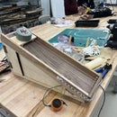
Step 1: Laser Cut Boxes and Wing and Then Construct


First, you need to cut the wood base, the acrylic main box, and the wing for the top of the motor. The wood base is 1/8" thick wood and the wing is 1/4". If you'd like to size your own boxes, you can go here, pick out your dimensions, make sure it is an open box with finger joints, download the files to illustrator, make the stroke 0.01mm, and color the lines that are meant to be cut out ff0000 and those that are going to be engraved 000000. For the wing, you can design it in illustrator using the pen. It's important to make sure you size it so that when the lights are attached, it doesn't touch any edges when the wing is spinning. The length of the wing plus the thickness of the LEDs on both sides should be shorter than the length of the acrylic box. If you use the files attached that's done. Then for each file upload it to ruby trotec, make sure your material is in the laser cutter and selected correctly in the software, refocus your laser, and then cut it. Once the boxes are cut, glue them together. For the wood base use a wood glue by placing glue on each side connecting and then placing. For the acrylic box, use acrylic glue, putting the box together first and then putting it on the connections. For both, clamp the box and let them dry for 24 hours. We will use the wood wing later.

Step 2: 3D Print the Servo Base

For the easiest build, simply download the file below. If you'd like to create it yourself, go to tinkercad and create a new project. My stand is 1.1" in width, 1.9" in length, and 5" in height. At the top there is a section cut out to place the servo into. This will depend on the size of your servo, but mine was 0.8" wide, 1.7" long, and 0.85" high and centered in the stand. I also had another gap in the top on the back wall of 0.375" so the wire could come out of the stand. I downloaded this as an stl file. Then take that file, or my file, and import it into the Prusa software. Make sure the printer can handle it, select the correct infill (mine was 15%), and then download it onto a flash drive. Plug the flash drive into the 3D Printer, load the filament, and then let it print. My file takes 4:20 to print.
Attachments

Step 3: Wire Up the CPBs


The first CPB will have the servo and the speaker attached to it. For the speaker attach one clip to the tip of the audio jack and connect that to the AUDIO pin. Then connect another clip to the base, and attach that to any ground pin. For the servo, the red wire should connect to VOUT using the alligator clip to male jumper wire. The black should be connected to any ground the same way, and the same with the white going to A2. For the second CPB, attach the LED as follows: the red wire connects to VOUT, the black to any ground, and the white to A1. Then for both connect the battery packs and make sure to put batteries in them.
Step 4: Download the Bluefruit Connect App
Step 5: Set Up CPBs and Download Code
If you're new to using the Circuit Playground Bluefruit, follow this video to learn how to set it up. Otherwise, make sure your CPB is set up and fully updated. Then download the code and audio file below. Move the GoalLightFirstBoard file and .wav file to the CPB attached to the speaker and servo. Put the .wav in a file named sounds. Then move the GoalReceiver2 file to the CPB attached to the lights. You can also find your own favorite team's goal horn here and can convert it to a .wav file to use instead. You can do this through the app Audacity. Make sure the file is in mono, set to 22 kHz, and at 16 bits or smaller.
Step 6: Hot Glue Base and Speaker


Now, we'll begin really putting it all together. The speaker is easy to hot glue, simply place it in the hole in the acrylic box, place hot glue, and let it sit for a few seconds, and it should harden and stay there. For the stand, first, find the middle of the base of your box. This middle point is where you want the center of the wing to be, which is not the same as the center of the servo. Place the white tip of the servo on the middle point, and mark how wide your servo is. From there, determine where the edges of the stand should go in order for the servo to be where you set it. Once you've outlined where it should go, simply hot glue the bottom of the stand to the base and place it where it should be. Then hot glue the top of the stand where the hole is, and then place the servo in there. The stand and servo should be steady in place.
Step 7: Screw Wing to Base of Servo


Find the center point of your wing. This is where the center of the blade should go. The blade along with the screws should come with the servo. Next, mark where the last two holes of the blade are on the wing. Drill an appropriate-sized hole in the wood on both of these spots and then drill a screw into the blade and wood in both of these spots. The wing can now be placed onto the top of the servo with ease.
Step 8: Tape Lights, CPB, and Battery to Wing


Wrap the led strip around the wing so that it fits perfectly, and then tape the strip with the packing tape to make sure it does not move. Then tape the battery pack to the center of the wing, so it doesn't make one side heavier than the other and finally tape the CPB in place to make sure it doesn't fly around. Make sure when you tape the battery pack you still have access to the on/off switch, and when you tape the CPB you have access to the USB port in case you'd like to make changes to the code. Place the wing on top of the servo.
Step 9: Tape Down Wires


To make sure nothing is sticking up and getting in the way, or getting caught, simply tape down the wires with packing tape. This will also make the project look nicer
Step 10: Turn on Battery Packs, Put Box Together, and Have Fun!

In the final step, we first need to turn on the battery packs. Then we'll place the acrylic box on top. And now we can use the light! Just go to the app, select your device (named "Goal"), select controller, control pad, and then press any button and watch it go!


![Tim's Mechanical Spider Leg [LU9685-20CU]](https://content.instructables.com/FFB/5R4I/LVKZ6G6R/FFB5R4ILVKZ6G6R.png?auto=webp&crop=1.2%3A1&frame=1&width=306)


