

Introduction: Home Automation Board With ESP8266 Dual Output


As technology advances, more and more people are turning to home automation to simplify their lives. From smart thermostats to voice-activated assistants, these devices are designed to make our homes more efficient and convenient.
But what if you could create your own custom home automation device tailored specifically to your needs? In this article, we'll show you how to build your own DIY home automation device that can control everything from your lights to your coffee maker.
This DIY home automation device uses an ESP8266 to operate two independent relays to switch two outputs or loads.
The user can visit the home automation device's WEB PAGE and utilize the buttons to operate the XYZ equipment connected to two relays.
In addition, if you're thinking about purchasing this board, checkout its tindie page-
http://www.tindie.com/products/makerpals/esp-automation-board/
Have a look at the Home Automation Board's building project.
Supplies
Material Required
These were the materials used in this built-
- Custom PCB
- ESP07S Module
- Relay 250V 10A Load side, 5V Operation
- 240V to 5V and 3.3V Isolated Power Supply
- AO3400 Mosfet
- 10K Resistors
- 1K resistors
- RED LEDs
- NODEMCU for programming the ESP07S
- M7 or SS34 Diode SMA Package
- Toggle Switch
Step 1: PCB Design
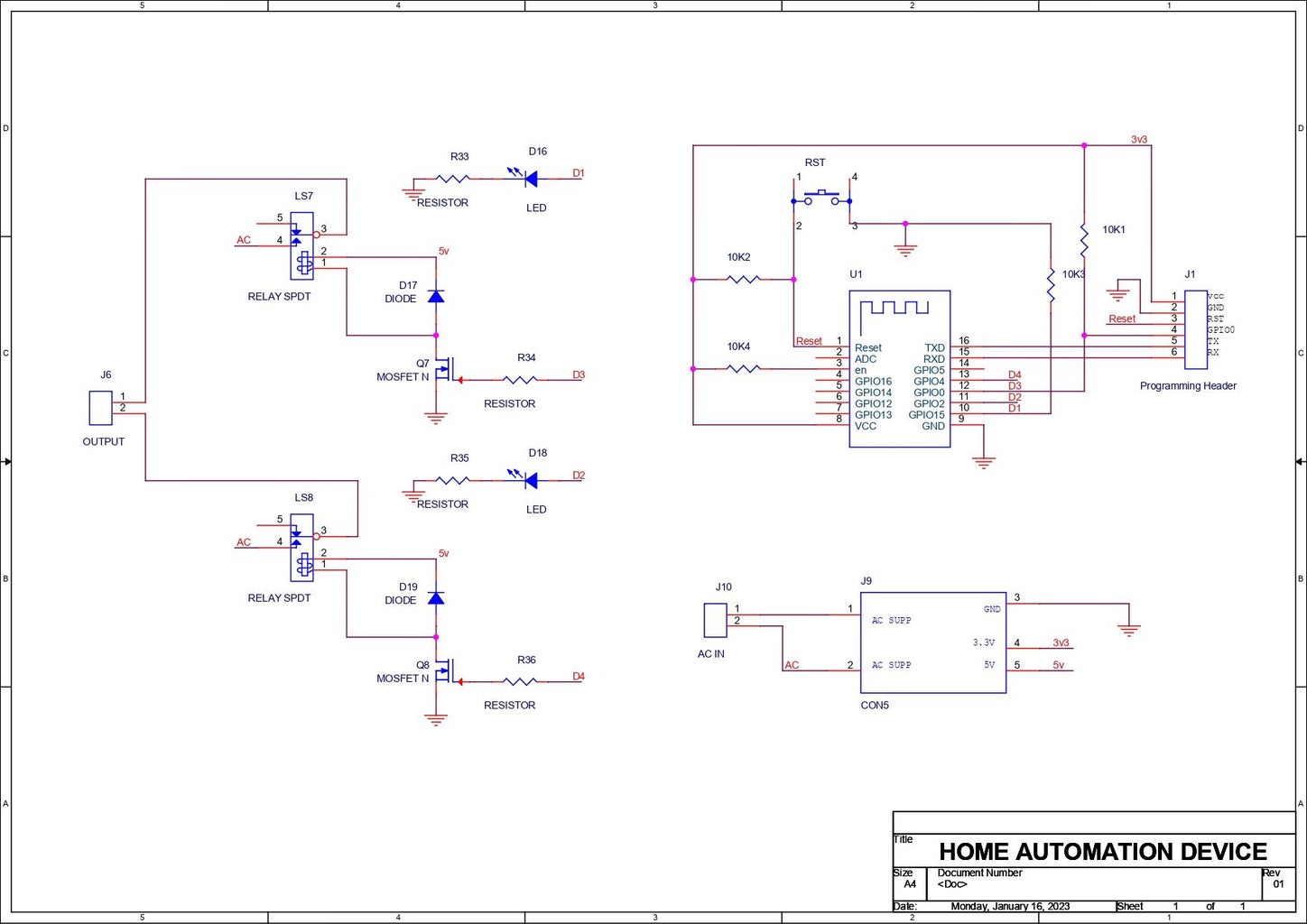
The first step is to create the PCB design for the home automation board, which consists of an ESP07S Basic Setup. The ESP07S is an ESP8266 board, and like all ESP8266 boards, it simply requires four 10K resistors linked to different GPIO pins.
We include two relays in the design to control the outputs. The gates of the relays are connected to GPIOs 4 and 0, and each relay is controlled by two N-Channel Mosfets set up in a switch configuration.
Also, we connect two LEDs to GPIO15 and GPIO2, which will be added near each relay when the components are placed on the PCB layout and will serve as an indicator when the relays are toggled.
This project does not incorporate an LDO, which is typically required when working with 5V input and ESP Modules to step down the 5V into 3.3V.
We utilize an AC-isolated power supply module in place of an LDO, which converts 240V AC into 5V and 3.3V filtered DC (It has two output voltages).
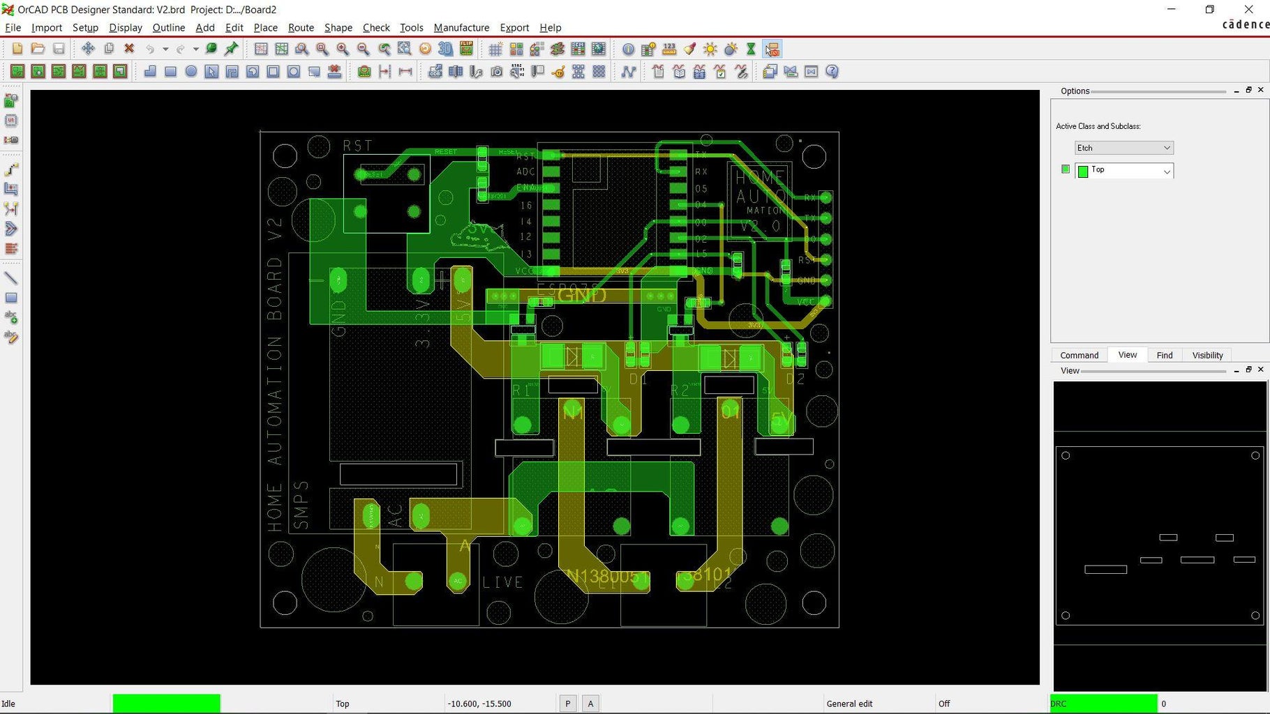
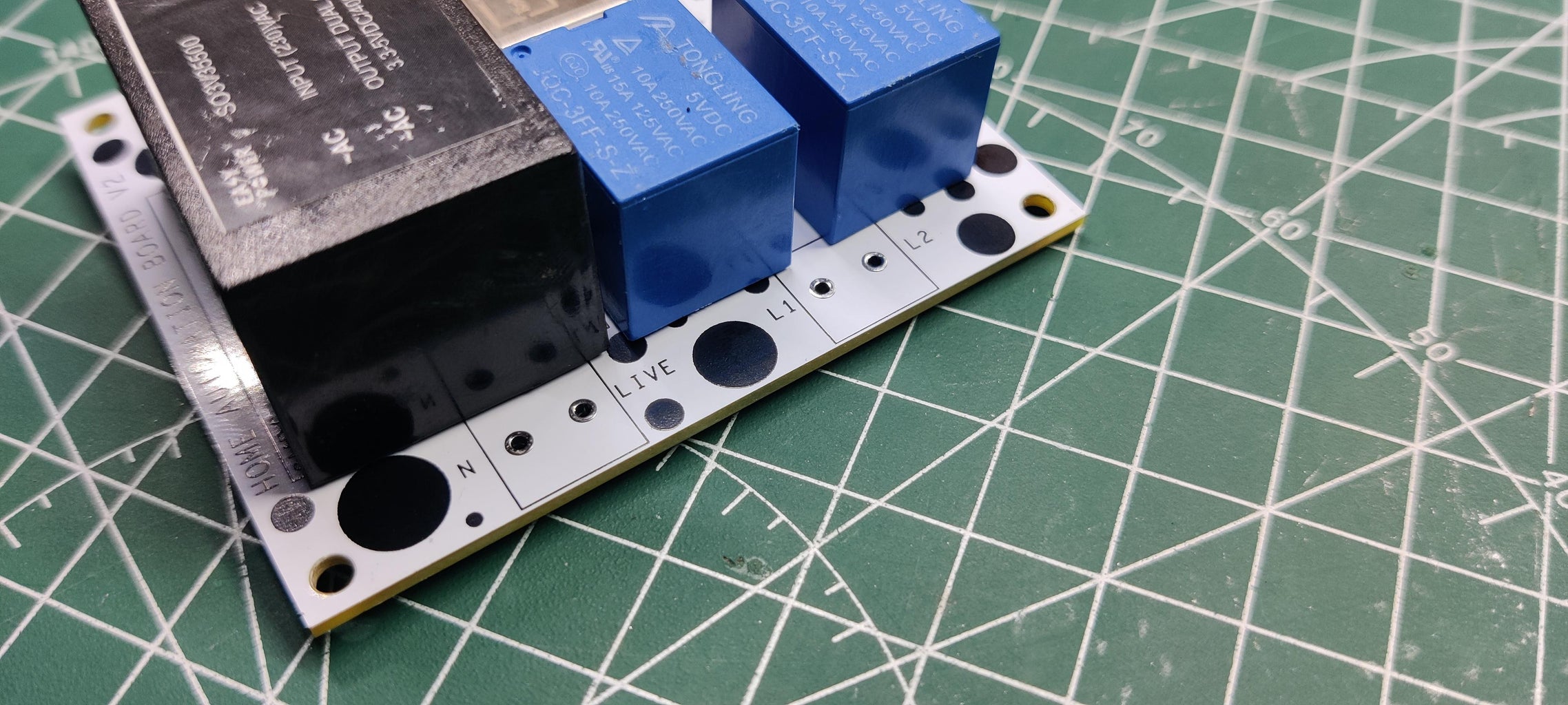
After the schematic is complete, we convert it into a board design and arrange all the parts in a neat 70mm x 60mm form factor.
A few slots were placed between the AC pins and the DC components for isolation purposes, and the ESP07S configuration is located on one side of the board while the other is occupied with relays and other components.
PCB Gerber Data was sent to PCBway for samples.
Step 2: PCBWAY

After the PCB Design was completed, Gerber data was generated and then sent to PCBWAY for samples.
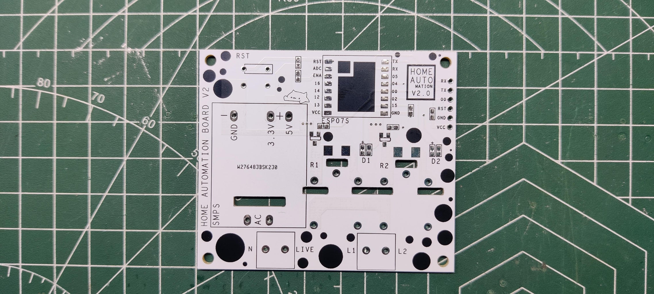
An order was placed for the PCBs with white soldermask and black silkscreen, as its looks pretty cool in general.
The PCBs were received within a week, and they were excellent, as expected.
Really love the quality of PCBs made by PCBWAY. There are other manufacturers available, but their service is always on another level.
check out PCBWay service for getting great PCB service at less cost.
Step 3: Board Assembly


- Board Assembly Process begins by first adding solder paste to each component pad one by one.
- Next, using a tweezer, we pick and position each SMD component in its designated location.
- Following that, we carefully lifted the entire circuit board and set it down on the Mini SMT Hotplate, which heats the PCB from below up to the solder paste melting temperature. As soon as the PCB reaches that temperature, the solder paste melts, and all the components are connected to their pads.
- The THT components are then assembled, and their pads are soldered using a soldering iron.
The board assembly is now complete.
Step 4: RESULT So Far

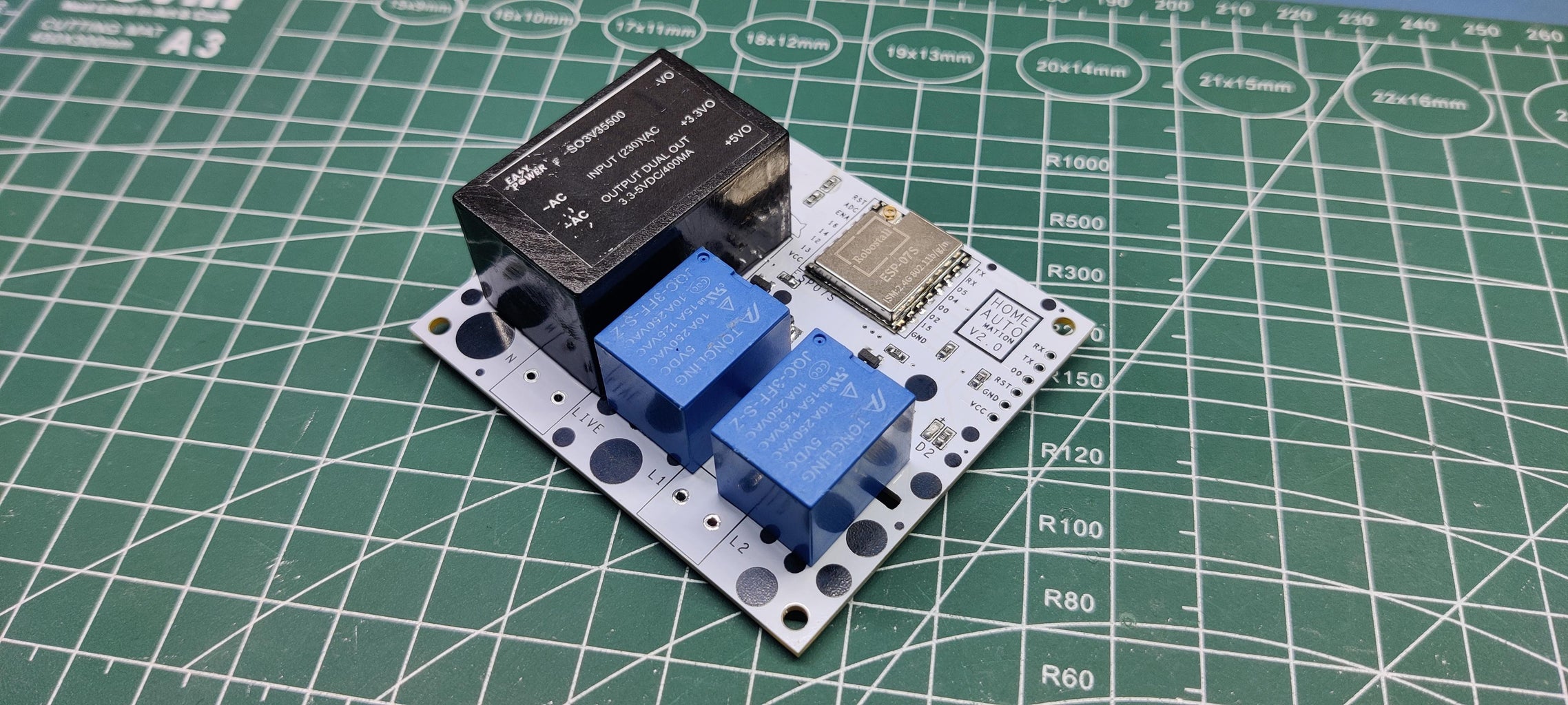

This complete home automation board, which has every component attached properly to its location, is the end result of the board assembly process.
We may now move on to the next step, which is programming the ESP07s so that we can use the board for controlling things.
Step 5: Programming the ESP07 With NODEMCU

You might not be aware that the NODEMCU Board can be used to program any ESP board.
By taking a NODEMCU Board and connecting a jumper with its GND Pin and EN Pin, which puts the ESP8266 of the NODEMCU into sleep mode, we may utilize the NODEMCU to program the onboard ESP07S module.
This enables us to connect an external ESP Board to NODEMCU; so essentially, we are turning off the ESP board on NODEMCU and connecting a second ESP Board to a few of its pins.
You can read the article below for additional information about this process.
Step 6: TEST SKETCH

The test sketch, which is actually a chaser sketch, is uploaded to the ESP Board. Its main function is to sequentially toggle each output pin to show how the board functions.
int pinsCount=5;                  // declaring the integer variable pinsCount
int pins[] = {0,4,15,2};          // declaring the array pins[]

void setup() {
  pinMode(0, OUTPUT);
  pinMode(4, OUTPUT);
  pinMode(15, OUTPUT);
  pinMode(2, OUTPUT);

}


void loop() {
  for (int i=0; i<pinsCount; i=i+1){    // chasing right
    digitalWrite(pins[i], HIGH);         // switching the LED at index i on
    delay(70);                          // stopping the program for 100 milliseconds
    digitalWrite(pins[i], LOW);          // switching the LED at index i off
  }
  for (int i=pinsCount-1; i>0; i=i-1){   // chasing left (except the outer leds)
    digitalWrite(pins[i], HIGH);         // switching the LED at index i on
    delay(70);                          // stopping the program for 100 milliseconds
    digitalWrite(pins[i], LOW);          // switching the LED at index i off
  }


}
After uploading the code, we unplug the board from the NODEMCU Programmer and attach an AC cord to the board's live and neutral connectors using a soldering iron.
The gates of the two MOSFETs that are connected to relays are attached to GPIO4 and GPIO0.
LEDs are connected to GPIO15 and GPIO2.
The chaser sketch ensures that each output is functional, allowing us to proceed to the next phase, which is to connect an AC load to the home automation board and upload the main code.
Step 7: OUTPUT WIRING


The hot side wiring is straightforward: we connect an alternating current supply to the board's AC CON, as well as live and neutral wires.
Live goes to each of the relay's COM ports; the NO of both relays is connected with a CON2 port.
By wiring components with this board in accordance with the wiring design, we may add a load by connecting it to the neutral and NO of the connector. With this configuration, we could also connect two loads.
Step 8: CAUTION


While working with an AC source, be sure to follow the fundamental precautions before wiring.
Do keep in mind that dealing with alternating current is dangerous and can kill you, so wear gloves, avoid touching the hot side of the board with your bare hand, and avoid lifting the board while it is connected.
Here is a hack that we can do while working with this board: We can 3D print a case for it that will isolate the AC connections and make it a little bit safer.
To test that the relay actually operates, we connected a 25-watt tube light to this board's load 1 and ran TEST SKETCH. The tube light flashed rapidly, as did the other outputs that were being turned ON and OFF sequentially.
Next, we upload the main code to this board
Step 9: Home Automation Sketch


Check out the main sketch, which is attached in the code section.
- We first edit the SSID and PASSWORD in the sketch
- next we upload the code into the ESP07S Module using the NODEMCU Programmer
- after uploading, we open the serial Monitor and copy the IP Address shown when the ESP gets connected to WiFi.
- We paste the IP Address in any browser and WEB APP will open up which can be used to toggle two outputs.
The web app is completely customized and is made completely from a single sketch without using any third-party tools.
This sketch is a fusion of classic embedded C language and HTML with a little bit of CSS.
We set up the HTML page in this sketch by the below lines.
// Display the HTML web page
            client.println("<!DOCTYPE html><html>");
            client.println("<head><meta name=\"viewport\" content=\"width=device-width, initial-scale=1\">");
            client.println("<link rel=\"icon\" href=\"data:,\">");
            // CSS to style the on/off buttons
            // Feel free to change the background-color and font-size attributes to fit your preferences
            client.println("<style>html { font-family: Helvetica; display: inline-block; margin: 0px auto; text-align: center;}");
            client.println(".button { background-color: #5B196A; border: none; color: white; padding: 16px 40px;");
            client.println("text-decoration: none; font-size: 30px; margin: 2px; cursor: pointer;}");
            client.println(".button2 {background-color: #5B196A;}</style></head>");

            // Web Page Heading
            client.println("<body><h1>HOME AUTOMATION DUAL OUTPUT</h1>");

            // Display current state, and ON/OFF buttons for OUTPUT1
            client.println("<p>LOAD1 - State " + output1State + "</p>");
We have 4 outputs (two relays and two LEDs), which were declared at the start of the sketch.
const int output1 = 0; //RELAY1
const int output2 = 4; //RELAY2
const int ledPin1 = 15; //LED1
const int ledPin2 = 2; //LED2
Please note that this setup will only work if the ESP8266 and the device that you're browsing the APP on the same network.(LOCAL NETWORK OPERATION)
Attachments

Step 10: Conclusion


The final result of this quick project is a Dual Load Home Automation Load that can be used to control two different AC Devices via a WEB APP.
The next iteration of this project will have more relays, which will increase the outputs.
Do leave a comment if you need any help regarding this project.
This is it for today folks.
Thanks PCBWAY for supporting this project, you guys can check them out if you need great PCB and stencil service for less cost and great quality.
And I'll be back with a new project pretty soon!


![Tim's Mechanical Spider Leg [LU9685-20CU]](https://content.instructables.com/FFB/5R4I/LVKZ6G6R/FFB5R4ILVKZ6G6R.png?auto=webp&crop=1.2%3A1&frame=1&width=306)


