

Introduction: Hot Glue Micro Servo Robot Arm


I once saw one of these micro servo robot arms on Youtube from back in 2014 and thought how clever it was, this particular one very delicately picked up a pieces of chalk and dropped them down a chute and just continued this over and over, the grabber was just made from a cable tie, the robot arm can be made from popsicle sticks or whatever you have to hand, all you needed really was some suitable material a 4 Micro Servos, 4 Potentiometers, Button switches and a Micro Controller and you are good to go.
The concept is this, you have one robot arm with potentiometers and when manipulating this arm the positions are mimicked on the arm with the Servos, pressing the button switch records movement so you could teach the Servo robot arm to carry out a function for as long as you wanted.
As with all things the concept sounds easy until you try to put it into practice and usually I fall at the first hurdle, but I'd like to give it a go.
The video which intrigued me on Youtube is by Pinaut and originally "Stoerpeak made me do it", so hats off to those guys for the concept, there are a few more videos on Youtube as well to go at.
Things have moved on since 2014, you could use something like the Pololu Maestro with their servo controller software which doesn't need an Arduino to carry out the moves and record and playback or you could do it the old fashioned way with the potentiometer record and playback, I quite like the old fashioned way where you are guiding the movement by hand.
With things moving on things have been made easier by using a servo shield as far as an Arduino build is concerned, making the connections that much simpler.
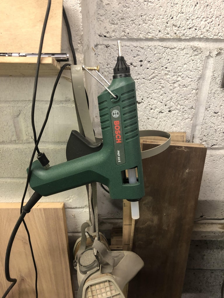
I have all the components to build the 2 robot arms, I have an Arduino Nano and Shield and some Micro servos, Potentiometers and Switches and more importantly some hot glue or hot snot as it's sometimes called:)
To the build:
Supplies

Arduino Nano c/w Servo Shield
4 x 90g Micro Servos
4 10k Potentiometers
4 x 10K resistors
Suitable material, I made from 3mm MDF sheet
Hot Glue
CA Glue
Ty Wrap or Zip tie
Cotton for the gripper action.
Hand drill and 1mm drill
9v Ba
Step 1: Building the Servo Robot Arm


With the the videos I looked at there are no dimensions for the robot arm, so its a best guess, One servo is hot glued in place upside down onto the MDF L Shaped base I used a servo horn with the biggest footprint for this.
Its best to use a Servo Tester and centralize the Servo before gluing, get it into the position where you want it then glue.
The next task is to cut the pieces of MDF and sand etc, I doubled the 3mm MDF pieces up to make the arm, for the upright which is hot glued to the side of the Servo, I made this 60mm, for the next arm, I made this 100mm and cut 2 slots out to accommodate the servos, they just push in from the side and are hot glued in position, the lower servo can now have the horn screwed into place and then this is hot glued to the 60mm upright giving clearance to the Servo below of course.
The Servo which controls the arm with the gripper, I cut 2 Pieces of MDF and shaped then sanded, then using a suitable horn I hot glued this into position, the last thing was the gripper arrangement.
This gripper made me smile a bit when I watched the video, its just a zip tie/cable tie I think, how ingenious, I had a few of these so I cut the length I needed then formed it with my teeth the zip side to the inside, pliers would be better and I don't recommend using your teeth, but I did, I couldn't find suitable pliers, this is a delicate gripper and it's worked by using thin cord, I made a couple of uprights for either side of the arm and secured the cable tie with hot glue.
A small hole is drilled either side of the gripper arm to accommodate the cotton which goes through one hole then through the opposite side and tied off, then from the centre of this tie a knot with another piece of cord and then push it through the centre hole in the cable tie and tie off at the servo horn the back and forth movement of the Servo closes and opens the gripper, I applied CA glue to each knot to secure.
I needed to extend a couple of the Servo Cables, I used Servo cable extensions for this, the other ends will be used for Potentiometer wiring.
So with this arm made we can now move onto the Potentiometer arm:
Step 2: Making the Potentiometer Arm


The Potentiometer arm doesn't have to be the same dimension wise as the servo arm, so I just used scraps of wood to make this, for the base I used a piece of broom shaft, cut to size and hot glued to the base, on top of this I glued a Potentiometer base down, to the rear of the piece of broom shaft I glued a potentiometer with a knob, then a 6mm piece of Dowel glued onto the knob to make a lever, this potentiometer is for the gripper.
For the shoulder I used just a small block of wood with a 6mm hole to accommodate the shaft of the shoulder Potentiometer, another potentiometer was Hot Glued on to the side of this for the elbow, the elbow was made from 2 pieces of 60mm x 24mm mdf glued together and a hole drilled in one end to accommodate the potentiometer shaft which was then hot glued into position, on the other end I hot glued a potentiometer with a knob, and a 6mm piece of dowel to make a control lever for the wrist action.
Ideally both the Servo arm and the Potentiometer arm should be facing in the same direction this is because the Servo Arm mimics the movement of the Potentiometer Arm and would make it awkward to judge movement etc.
Time to make the connections.
Step 3: Making the Connections


The electrical connections are really easy when using a Servo shield.
Servo 0 Pin 3
Servo 1 Pin 10
Servo 2 Pin 9
Servo 3 Pin 11
Just push the connectors onto the pins ensuring you have the 5v Gnd orientated correctly.
Potentiometer connections are.
A0
A1
A2
A3
For these connections and to make things easier, I just cut up 4 Servo Extension cables and soldered these to the Potentiometer pins the data pin or wiper pin is the centre pin, 5v to the Left pin Gnd to the right Pin, then connect the Potentiometer connectors as you would a Servo connector to the shield pins.
There are 2 momentary button switches to wire in as well, I just used a small perf board for this, I took a 5v and Gnd from the shield and soldered these onto the end pads on the perf board I then soldered a couple of switches onto the board, then soldered a 10K pull down resistor to one leg of the switch and soldered this to the 5v Supply, the data cable is soldered onto that same leg on the switch, I made a solder bridge and then the other leg of the switch has a Gnd soldered onto it to make the circuit, the record and playback switch data cable goes to Pin 6 on the shield, the same process is applied to the 2nd Switch, this is a pause switch, the data cable for this goes to Pin 4 on the shield.
To complete the wiring I soldered a 9v Battery connector to the Vin and Gnd Pins on top of the Nano, Job done! Time to test.
Step 4: Testing the Robot Arm
First of all I uploaded the Arduino code, I got this code from the Pinaut video, there is a link to a website with info about the build, the code is in there.
I connected the 9v battery and guess what? nothing! Nada! Zilch! there should be movement straight away when moving the Potentiometer arm, I pressed the record button in and I had movement as long as the button was pressed, that's not right, hmm so I checked the wiring then noticed I'd got the data pins from the buttons the wrong way round, school boy error so swapping these had the arm up and running.
On the original video the robot arm picks up a piece of chalk and drops it down a chute and this is recorded and off it goes, when the guy is adjusting the Potentiometers they stay in position, unfortunately the Potentiometers I had didn't have enough friction to hold position and just dropped at every opportunity making it really hard to record, plus the Servo arm had the shakes as well, I don't know if this was me shaking or the Servos:)) but all this made things difficult to record something.
Anyway how you record movement:
Step 5: Recording Servo Arm Movement
Plug in the power and the set up your first move, every move you make you press the record button once and when you are happy with your scenario you quickly press the record button twice and it will play the moves.
Unfortunately and as described earlier it was difficult to record anything with finesse as the potentiometers I had used would not hold position, I did a couple of short videos showing some recorded movement just to see it in action but the principal worked fine, a great little project to have a play with,
My assumptions:
Step 6: Assumptions
I think if I had another go at making one of these, I would use a firmer base, you don't want the base moving around when you are recording a sequence.
I would also make sure I got the correct Potentiometers, Its very clever moving the arm about and recording the movement, and you could come up with any number scenes for the arm to re enact.
Another solution would be to have the Potentiometers fastened in line on a piece of wood, this would eliminate the arms dropping and make it far more precise, and something which I may try later.
On the whole a really easy project, especially using the Servo Shield, and great fun too!
I hope you enjoyed this Instructable and thanks for looking.

Participated in the
Hot Glue Speed Challenge


