

Introduction: How to Design a Parametric Bench With SelfCAD


Learn how to design a parametric bench with SelfCAD
Step 1:
How to Design a Parametric Bench with SelfCAD
Welcome to this comprehensive tutorial on creating a parametric bench using SelfCAD!. Whether you're an experienced designer or a novice entering the world of 3D modeling, this tutorial will walk you through the process of creating a versatile and customizable bench using SelfCAD. Parametric design, which allows for easy manipulation of dimensions and features, is at the heart of this tutorial, offering flexibility for various settings such as gardens, parks, or outdoor spaces. With SelfCAD's user-friendly interface and powerful parametric tools, you'll not only craft a stunning bench model but also gain valuable insights into navigating the software for future projects.
The interactive tutorial to this article can be accessed at https://www.selfcad.com/tutorials/w4azv6i3j3w2o5fj3j5o682a6s162a6d6e1w
To design with the help of a Youtube video, check out https://www.youtube.com/watch?v=48LFZiRNTkQ
Once you’ve launched the editor;
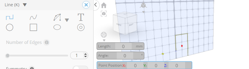
From the Drawing Category on the Toolbar choose 3D Sketch
From the plane list select: Left/Right (plane list can be found in Plane Settings). From the plane list deselect: Bottom/Top (plane list can be found in plane settings)

Set Left/Right plane Offset to-250(this parameters can be found in plane settings)

Set Snap To Grid Vertices to true (this parameters can be found in Precision Settings)
Click on highlighted point to draw edge


Click on highlighted point to draw edge

Click on highlighted point to draw edge

Click on highlighted point to draw edge
Click on highlighted point to draw edge

Click on highlighted point to draw edge

Click on highlighted point to draw edge

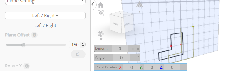
Set Left/Right plane Offset-150 (these parameters can be found in plane settings).

Click on profile_1 to deselect it.
Click on highlighted point to draw edge

Click on highlighted point to draw edge

Click on highlighted point to draw edge

Click on highlighted point to draw edge

Click on highlighted point to draw edge

Click on highlighted point to draw edge
Click on highlighted point to draw edge

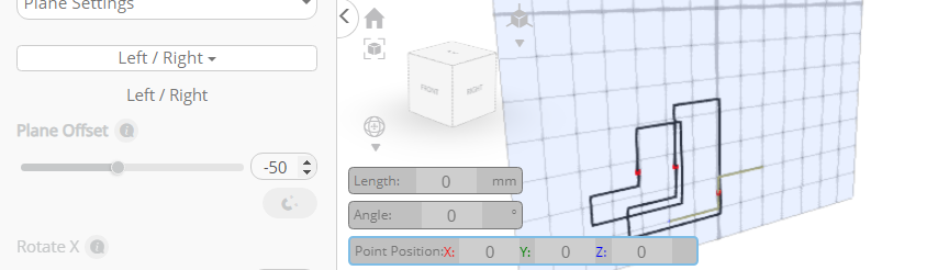
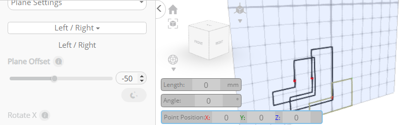
Set Left/Right plane Offset-50 (these parameters can be found in Plane settings)

Click on profile_2 to deselect it.
Click on highlighted point to draw edge


Click on highlighted point to draw edge

Click on highlighted point to draw edge

Click on highlighted point to draw edge
Click on highlighted point to draw edge

Click on highlighted point to draw edge

Click on highlighted point to draw edge
Click ‘X’ to close 3D Sketch panel
Click on profile_2, profile_1 to select it.
From the utilities Category on the Toolbar choose Mirror or use shortcut (U+I). Set Create Copy to true. Set Direction to right,Offset to 50.
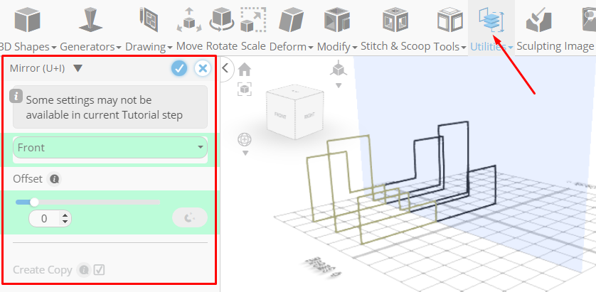
Tick the check mark (upper left corner) to finalize Mirror.

Click on profile_3 (1), profile_2 (1), profile_1 (1) to select it.
From the Modify Category on the Toolbar choose Round object or use shortcut (M+R).
Set Convert To spline to true.

Tick the check mark (upper left corner) to finalize Round object.

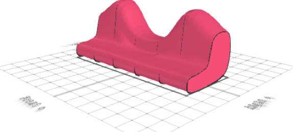
From the Tools Category on the Toolbar choose bridge or use shortcut (T+E).
Set Linear to False, Smoothness to 6.

Tick the check mark (upper left corner) to finalize Bridge.
Click Color Picker button to change color of selected object.
Click Red button to change color of selected object.

Click OK button to confirm color change.
From the 3D Shapes Category on the Toolbar choose Cube or use shortcut (P+C).
Set Width to 5,Height to 220, Depth to 250, Position X to -240.

Tick the check mark (upper left corner) to finalize cube.
From then Tools Category on the Toolbar choose Copy offsets or use shortcuts (T+P).
Set X to 10. Set Amount Of Copies to 48.

Click Copy button to create copies.

From the Edit Menu on the Top Toolbar choose Group or use shortcut (Ctrl+G).
Click ‘X’ to close Copy offsets panel.
Click Color Picker button to change color of selected object.
Click Orange button to change color of selected object.

Click OK button to confirm color change.

Click on mesh_1 to select it.
Click Stitch & Scoop on the Toolbar or use shortcut (B). From the tool panel choose Difference or use shortcut (B+D). Choose group_1 to subtract.
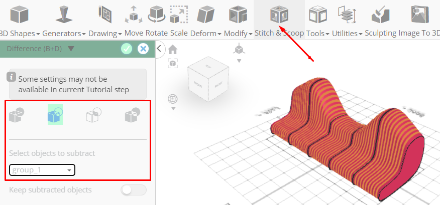
Tick the check mark (upper left corner) to finalize Difference.
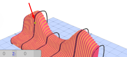
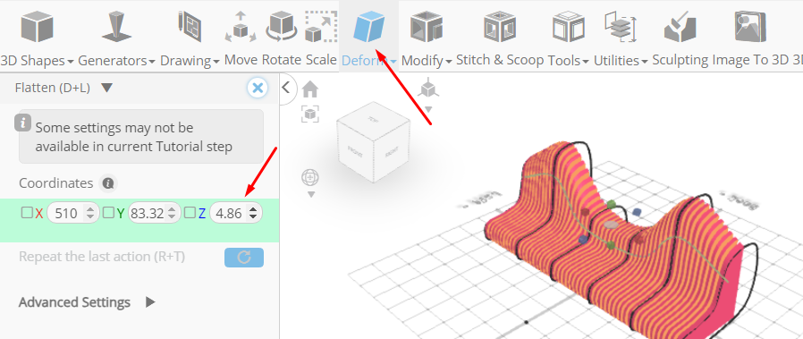
From the Deform Category on the Toolbar choose Flatten or use shortcut (D+L).
Set y to 192.96 using highlighted gizmo. Set z to 150.02 using highlighted gizmo.

Click ‘X’ to close Transformation panel.
From the Drawing Category on the Toolbar choose 3D Sketch or use shortcut (K).
From the tool panel choose Circle or use shortcuts (K+C).
Set Number of Edges to 18.

From the plane list select:Bottom/Top (plane list can be found in Plane Settings).
From the plane list deselect:Left/Right (plane list can be found in plane settings)

Click on highlighted point to draw circle.

Type in 2 value into the Radius measurement.

Click on highlighted point to draw circle.

From the tool panel choose Spline or use shortcut (K+S).

Click on profile_4 to deselect it.
Click on highlighted point to draw spline.

Click on highlighted point to draw spline.

Click on highlighted point to draw spline.

Click on highlighted point to draw spline.

Press Esc to stop drawing stroke.
Click ‘X’ to close 3D Sketch panel.
From the Utilities Category on the Toolbar choose Mirror or use shortcut (U+l).
Set Create Copy to true. Set Direction to right.

Tick to check mark (upper left corner) to finalize Mirror.
Click on profile_5 (1) to select it.
From the Edit Menu on the Top Toolbar choose Merge or use shortcut (Ctrl+M).
From the Deform Category on the Toolbar choose Flatten or use shortcut (D+L).
Set z to 0.
Click ‘X’ to close Transformation panel.
From the Modify Category on the Toolbar choose Round object or use shortcut (M+R).

Tick to check mark (upper left corner) to Finalize Round object.
Click Move on the Toolbar or use shortcut (M).
Set Z to -28
Set x to 0.

Click ‘X’ to close Transformation panel.
Click on profile_5 to select it.
From the tools Category on the Toolbar choose Follow path or use shortcut (T+P).
Set Mode to extrude.

Tick to check mark (upper left corner) to finalize Follow path.
Click Color Picker button to change color for selected object.
Click Orange button to change color for selected object.

Click OK button to confirm color change.
From the 3D Shapes Category on the Toolbar choose Cylinder or use shortcut (P+Y). Set Top Radius to 2, Bottom Radius to 2, Height to 508, Horizontal Segments to 32, Position Y to 22, Positon Z to -28, Rotation Z to 90.

Tick to check mark (upper left corner) to finalize Cylinder.
Click Color Picker button to change color for selected object.
Click Orange button to change color for selected object.

Click OK button to confirm color change.
From the Utilities Category on the Toolbar choose Mirror or use shortcut (U+l).
Set Create Copy to true.
Set Offset to 50.

Tick to check mark (upper left corner) to finalize Mirror.
Click on mesh_10 (1), mesh_6, difference_1 to select it.
Click Isolate button to isolate selected object or use shortcut (V+l).

From the Deform Category on the Toolbar choose Bend or use shortcut (D+B)
Set Plane to Left/Right (Some parameters can be found in Advanced Settings).
Set z to 60.

From the Deform Category on the Toolbar choose Taper

Click on mesh_10, mesh_10 (1) to deselect it.
Set Plane to Left/Right
Set y to -32
Click ‘x’ to close Transformation panel

As you continue honing your design skills, remember that SelfCAD offers a wealth of resources to support your learning journey. To deepen your understanding and explore more advanced features, consider checking out the interactive tutorials available on the SelfCAD website. The tutorials page provides a treasure trove of guides, tips, and tricks that cater to designers of all levels.
More structured learning experience can also be accessed at the SelfCAD Academy and 3D Modeling 101 series. This comprehensive resource offers in-depth courses taught by industry experts, allowing you to master the intricacies of SelfCAD at your own pace.


![Tim's Mechanical Spider Leg [LU9685-20CU]](https://content.instructables.com/FFB/5R4I/LVKZ6G6R/FFB5R4ILVKZ6G6R.png?auto=webp&crop=1.2%3A1&frame=1&width=306)


