Introduction: Making Your Own Photovoltaic 5V System
This uses a buck converter as a 5V Output to charge the battery(Li Po/Li-ion). And Boost converter for 3.7V battery to 5V USB output for devices needed 5 V. Similar to the Original system that uses Lead Acid Battery as an energy storage charge by either PWM or MPPT controller. And supply for 12V Devices. This One only uses a Buck converter to convert 12V (solar panel nominal voltage) to stable 5V to charge a Li-Po/Li-ion battery, after daylight. Switch to Boost converter to convert the battery's voltage 4.2 (3.7 nominal voltage for Li-Po and Li-ion) to again 5V for devices powers 5V. (You can still use the 5V in the Buck Converter during daytime while the Li-Po/Li-ion Battery is charging. It might not be as efficient as the original system(12V). I only did this because my solar panel power is only 15W and not enough budget to buy MPPT or PWM charger for 12V. and not enough to power applications that need higher than 50W. So I make an alternative option, the 5V version.
(Reminder, the system does not have any controllers.)
This system is for solar panels that are lower than 30W and only 12V only. (9V solar panels would still work).
My System specifications
Input Solar Panel =12V (18V)
Power used = 15 W
Charging time = depends on your solar panel's power and the battery’s capacity.
USB Output 1 (Buck converter) = 5V
USB Output 2 (Boost converter)= 5V
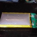
Battery type= depends on your choices(Li-Po/Li-ion) 3.7 and capacity - Mine was Li-Po with a capacity of 3500mAh.
One to point:
While the project is ongoing for experiments for improving and calculating its efficiency and whether it was worth it. Ask me questions for the project.
Step 1: Ready the Materials
- Purfboard (Medium Size)
- Wires
- Leads Alligator Crocodile Double-ended Test Roach Clip Jumper Wire( Optional for testing)
- 2x USB Ports
- Lead solder.
- Solar Panel -(recommend 20Watts higher, 12V)
- 1x TP4056 charging and protection circuit for the Li-Po and Li-ion.
- 1x Li-Po/Li-ion battery ( depends what battery you choose and the capacity)
Buck-Converter (One I use)
- (1x) LM2576T (5V version, 3A )
- (1x) 100uH Inductor
- (1x) 100uF and (1x) 1000uF Electrolytic capacitors
- (1x) Schottky Diode
- (1x 1K resistor and small LED) -optional
Along with measurement tools
- Digital/Analog Multimeter ( Voltage and Current needed here to calculate its efficiency)
Step 2: Follow the Circuit Schematic
Solder all the components in a PCB purfboard.
It would be better to short the Data plus and minus Pins on the USB ports for Android Phones.
be sure to switch off the Boost converter to not overload the TP4056 while charging the battery.
If your solar panel's power is lower than the recommended power, which is 20Watts above, you should only connect one battery. because of the limited power in your solar panel's power. Example: 15Watts is 0.83A, which means that's your max current.
Step 3: Power and Measure the Circuit.
If the circuit is working properly, then test it by using dummy loads like 5W resistor in the output and measure the voltage and current. like this picture.
Encountering Problems
- photovoltaic system -
If the input voltage (photovoltaic) in the buck-converter suddenly drops lower than the nominal voltage of PV and the output voltage. then the problem should be on this list.
*the load in the output is connected already and draws more power from the PV.
*Less sunlight outside due to cloudy, etc.
if your problem is not on this list, leave a comment and I will answer it.
Step 4: Finished
We're done.
You can calculate the efficiency of the Buck-converter and the Boost converter by this formula.
Output Voltage x Output Current
------------------------------------------- x 100% = Efficiency
Input Voltage x Input Current
Things to Remind!! - Always switch off the connection between Battery and the Boost-Converter to not overload the TP4056 charging process during the daytime. only use it for Tonight.
- be sure that there are batteries charging when measuring the current and voltage to get its efficiency.
Advantages and Disadvantages
+ 5V operated. For charging and powering applications that need 5V
- Not for applications that needs 12V/9V.(Can be adjusted if your boost converter is adjustable)
+ Efficiency rate is good enough. ( Mine are 70% in buck converter and 68% in Boost converter)(Little bit higher if you use an already build the module.)
- The efficiency may drop if the input of buck converter voltage drop. Due to the output draw power.
+ Inexpensive system
- System without a Controller (to monitor the battery and the solar charging status and protections)
+ Easy to make if buying the already built boost and buck module.
One thing to point out:
The limited current output of the buck-converter is depended on your solar panel's power (Watts). My solar panel's power is 15 Watts, which means I'm limited to the current of 0.75A when connecting to the charger. This is why I recommend a solar panel that at least higher than 20W.
Feel free to comment if you have questions about the project.
If you make your own Photovoltaic 5V System. please share.
You can follow me on any social media. So that you can
Follow me on Facebook and Twitter
Facebook: https://www.facebook.com/Desmotronics
Twitter: https://twitter.com/Desmotronics
Subscribe to my Youtube channel: https://www.youtube.com/channel/UCpbIpRrQN2hFMLuCf...
Visit my website: https://electronichobbyist.wixsite.com/main
Reminder: Always have knowledge about electronics and think about safety first before, during, and after making the project. Safety First.


