

Introduction: IMPLEMENTING AN LED BLINKING EXPERIMENT

With STM32 black pill and STM cube IDE to implement a sequence where three LEDs blink in various combinations
In this tutorial, we will delve into programming the STM32 "Black Pill" development board using STM32CubeIDE to create diverse LED blinking patterns. The Black Pill board employs the STM32F103C8T6 microcontroller, while STM32CubeIDE serves as a robust integrated development environment tailored for STM32 microcontrollers.
Supplies
- STM32 Black pill
- 3Led's
- Breadboard
- Jumper Wire
- USB type C cable
- STM 32 Cube ide
- STM 32 Cube Programmer
Step 1: Setting Up Stm Cube IDE

- Download and install STM32CubeIDE on your computer.
- Launch STM32CubeIDE and initiate a new project. a. Select "New STM32 Project" from the Quick Start menu. b. Choose your board or microcontroller (STM32F103C8) and proceed with the Next option. c. Configure project name and location, then click Finish.
Step 2: PINOUT Configuration


- Select RCC from System Core.
- Select the Cereamic/crystal response in High speed clock.
- Some configurations wlll be added ,i.e,RCC_OSC_IN & RCC_OSC_OUT ON STM32 board of cubeide.
- Select the Pins for output .(here I used PA10,PA11,PA12).
Step 3: CLOCK CONFIGURATION

- Select clock configuration.
- Select HSE and PLLCLK in PLL Source MUX & System Clock MUX respectively.
- Then select resolve clock issues
Step 4: Write the Led Blinking Code
HAL_GPIO_WritePin(GPIOA, GPIO_PIN_5,0);

  HAL_GPIO_WritePin(GPIOA, GPIO_PIN_6,0);

  HAL_GPIO_WritePin(GPIOA, GPIO_PIN_7,0);

  HAL_Delay(1000);

  HAL_GPIO_WritePin(GPIOA, GPIO_PIN_7,1);

  HAL_Delay(1000);

  HAL_GPIO_WritePin(GPIOA, GPIO_PIN_6,1);

  HAL_GPIO_WritePin(GPIOA, GPIO_PIN_7,0);

  HAL_Delay(1000);

  HAL_GPIO_WritePin(GPIOA, GPIO_PIN_6,1);

  HAL_GPIO_WritePin(GPIOA, GPIO_PIN_7,1);

  HAL_Delay(1000);

  HAL_GPIO_WritePin(GPIOA, GPIO_PIN_5,1);

  HAL_GPIO_WritePin(GPIOA, GPIO_PIN_6,0);

  HAL_GPIO_WritePin(GPIOA, GPIO_PIN_7,0);

  HAL_Delay(1000);

  HAL_GPIO_WritePin(GPIOA, GPIO_PIN_7,1);

  HAL_Delay(1000);

  HAL_GPIO_WritePin(GPIOA, GPIO_PIN_6,1);

  HAL_GPIO_WritePin(GPIOA, GPIO_PIN_7,0);

  HAL_Delay(1000);

  HAL_GPIO_WritePin(GPIOA, GPIO_PIN_6,1);

  HAL_GPIO_WritePin(GPIOA, GPIO_PIN_7,1);

  HAL_Delay(1000);
Step 5: Building the Project
- Connect your STM32 Black Pill board to your computer using a USB cable.
- Build the project by clicking on the hammer icon in the toolbar.
- Once the build is successful, click the play (debug) button to flash the code onto the board.
Step 6: Testing the Led Blinking Pattern
- Navigate to the "Core" folder in the project explorer and open main.c.
- Include necessary libraries and header files.
Step 7: Led Blinking Results
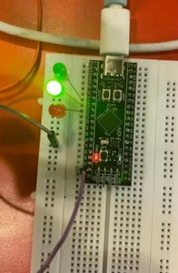
The STM32 Black Pill board to control LEDs in different blinking patterns using STM32CubeIDE. we can do further by adding new patterns or modifying the existing code to create more complex LED sequences.


![Tim's Mechanical Spider Leg [LU9685-20CU]](https://content.instructables.com/FFB/5R4I/LVKZ6G6R/FFB5R4ILVKZ6G6R.png?auto=webp&crop=1.2%3A1&frame=1&width=306)


