

Introduction: IoT Automatic Watering Plant


Hydro M8 Bina Nusantara University Computer Engineering
By:
1. Frederico Godwyn Pratama Dewat M - 2502029433
2. Nicholas Oliver Marvin S - 2540120894
3. Nathanael Pandu Winarta - 2502020604
4. Kenny Christiano Alvarez - 2540119482
Farming is one of the hobbies that many people like. but not everyone has the time to constantly watch their crops. This can be caused by various reasons, starting from busy work, taking care of the family, and other activities. Seeing the problems that arise, the author is moved to design a tool that can help those who are busy in maintaining the condition of their plants so that they remain optimal during the growth period.
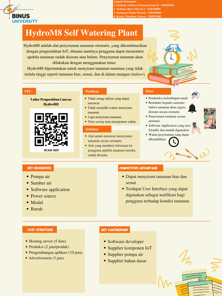
HydroM8 is an automatic plant sprinkler, which implements an IoT system, where later users can water plants remotely. Watering the plants can be scheduled or carried out independently according to the wishes of the plant owner. HydroM8 is intended for watering plants that are not too tall, such as ornamental plants, seedlings, and our tools are specifically for indoor.
With this tool, the authors hope to make it easier for plant owners who don't have time to care for plants, especially watering plants that are maintained because this tool can water automatically according to an existing schedule or users can water independently via the button on the application that has been provided.
Supplies
- 1/2" PVC pipes
- 5/8" PVC pipes
- 3D Printing Parts
- GT2 6mm wide bel
- GT2 20T pulley bore 5 mm
- GT2 Idler pulley bore 5 mm
- Nylon cable tie
- 28BYJ - 48 12V stepper motor
- ULN2003 stepper motor driver board
- 12v Submerge Pump
- ESP32
- LED
- IRF540 MOSFET
- BJT BC547
- Limit Switch
- Electrical Wire
- Electrical Tape
- 5v 1A or 2A Power Supply
- Acrylic Plate
- Elbow pipe PVC Connecter
- DHT11 Sensor
- OLED Adafruit Display 128 x 64
- Soil Moisture Hygrometer Sensor
- LED Strip
- 5 Volt Power Supply
- Steel Rod 30 cm
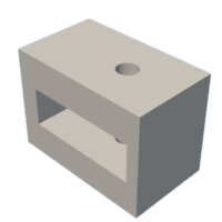
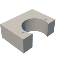
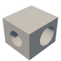
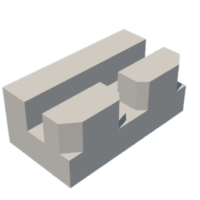
Step 1: Print 3D Print Parts
Prepare filaments needed for 3D print parts. The parts can be printed as the STL file attached below
Step 2: Assemble the Hardware
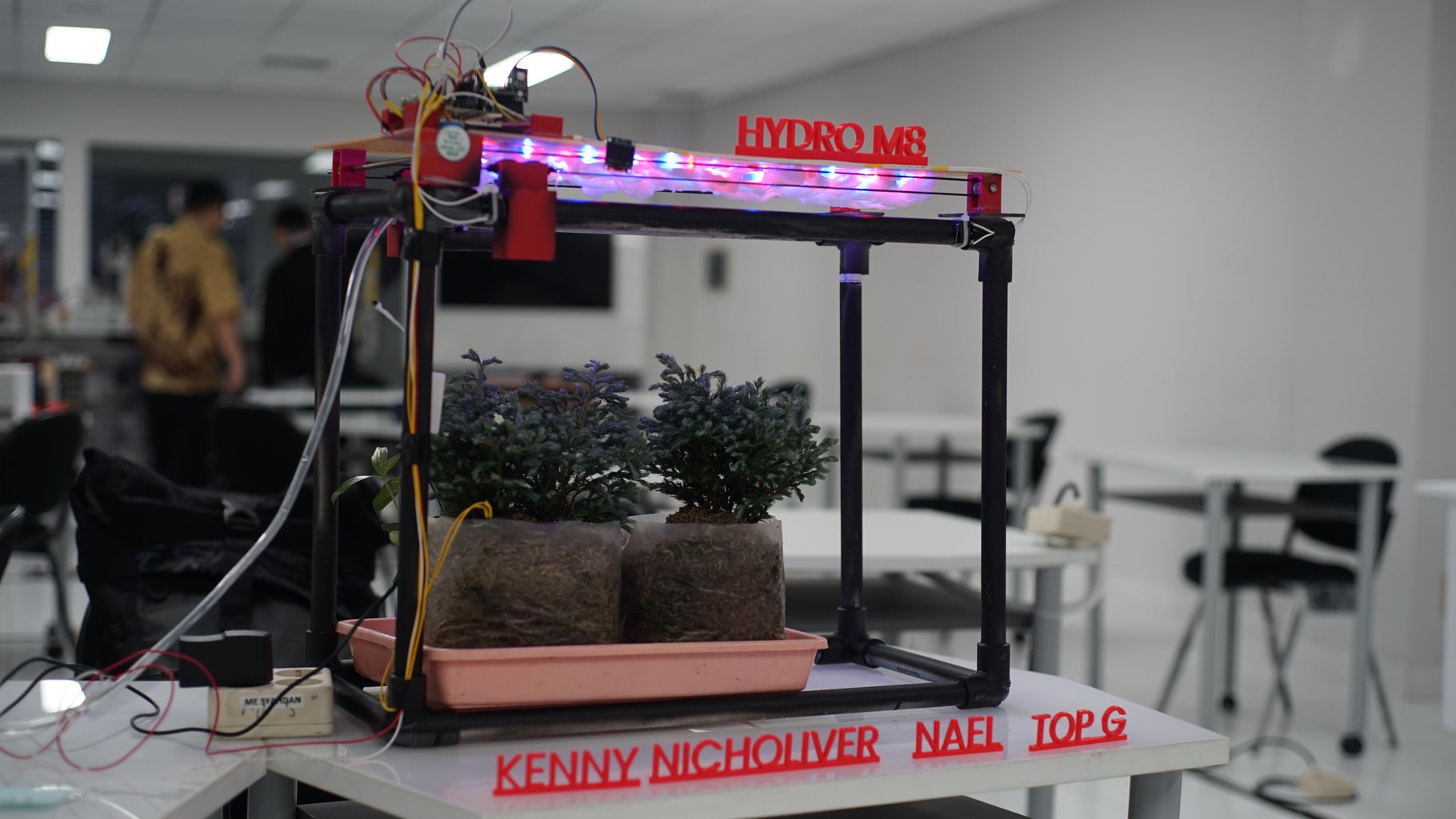
Assemble the Hardware as shown in the picture above.
Assemble the base frame for the project using the 1/2" PVC Pipes into a block shape and use the pipe PVC elbow connectors. Attach the tube to the 3D printed linear slide part and glue the edge with glue gun
Step 3: Setup Main Code


This is the main code that we use to develop our IoT project. In this code that we have provided, it is the latest version. the libraries are all included in the platform.ini. We coded our program using Semaphore RTOS since there will be some programs that will be executed at the same time.
Our void setup is used to setup some initial values from the GPIO pin such as the MOSFET pin, Stepper motor, the limit switches and also setup for the OLED display to be able to display. We also locate the wifisetup() void in the void setup so that the ESP32 understands that it needs to connect to the Wi-Fi as it begins to initiate the program. In the void setup we also give out each void the function for its own semaphore task and give stack sizes for each void. After that we configured the void wifiSetup that we use to connect to WiFi. in this case we are using the WiFi manager (Libraries will be included in the platform.ini)
Afterwards the ESP2 will try to connect and authenticate to the Firebase that its connected to. The ESP32 will then fetch from the firebase. In this case it will be in the form of JSON data as we have a feature of user able to set alarm for when to water the plant and thus it fetches the initial information for the Boolean value of each day from Monday to Sunday.
Once it is connected, the ESP32 will configure the NTP and gets the time directly from the NTP server with small configuration from our program to change it into Indonesia current time as per Waktu Indonesia Barat.
Then it will read the humidity from the DHT11 sensor and also the soilmoisture sensor. After that it will update the data that the sensor has fetched from the previous void and updates it to the firebase. Both for the RTDB and the Firestore. We use the RTDB to fetch the data in real time as the sensor detect changes from the surrounding environment. As for the Firestore, we configure it so that it's able to store the data historically.
Here is the link to the Github:
https://github.com/nicholiver/HydroM8_Hardware.git
Step 4: Flutter Application Design


Here we have the mobile application developed by using flutter. The code will be represented in the Github link below for reference. In the mobile application, we have the homepage view of mobile Apps showing RTDB Temperature, Humidity and Soil Moisture data. We also designed a Button that functions to send boolean data to firebase. If the boolean value is true then the system will start to run and water the plant.
The temperature page, Humidity page and soil moisture sensor page all shows RTDB temperature data, chart and history of temperatures
And lastly there's a page that shows the time to water the plants automatically and the data is saved to firebase.
Here is the link to the Github:
https://github.com/ricogod/Code_TR_IOT_HydroM8/commit/84b764bac725c4cdb0c28dbca33be9280f51adfb
Step 5: Setup Firebase


In this step we would setup the Firebase for the RTDB and the Firestore. We configured the RTDB to fetch the real time data from the sensor that it fetches and the Firestore is used to store historical data.
Step 6: Flowchart


This is the flowchart for our system and program.
Step 7: Block Diagram

This is the Block Diagram for our system and program
Step 8: Conclusion
Conclusion :
- Real-time watering system success rate is 100%
- Scheduling system success rate 70%
- Data can be sent seamlessly to firebase
- The tool works optimally when the internet and resources are stable
Suggestion :
- After the various processes we have done to make this tool, here are suggestions for improving our tool:
- Use of better sensors for more optimal data quality
- The use of a sprinkler nozzle so that the distribution of water is more thorough
- A cover is made around the tool so that water does not spread everywhere
- The use of a stepper that is stronger, as well as materials for a better structure so that the movement of the tool is smoother.
- Memory management code from the ESP32 that can still be optimized.

Step 9: Demo Video
This is the video demo of our project


