

Introduction: JOYCON Button and Analog Stick Board


Hey folks, how are you?
So let's look at something helpful. The JOYCON board is designed for prototyping any project involving buttons or joysticks, is breadboard friendly, and has buttons and analog sticks.
This board was made with the intention of using an ESP32 microcontroller to build a game controller.
I also wanted to build a breadboard-friendly system that would allow me to swap out the ESP32 board with another board if necessary.
The goal was to create a board that could be tested before moving on to the next edition, which would include an ESP32 Wroom microcontroller with buttons and a joystick.
Supplies

The following are the materials used in this project-
- CUSTOM PCB
- Toggle Buttons
- Analog Joysticks with cover
- Male Header Pin connector
- Breadboard
- ESP32 Board
- Jumper wires
- Arduino Nano
Step 1: PCB Design


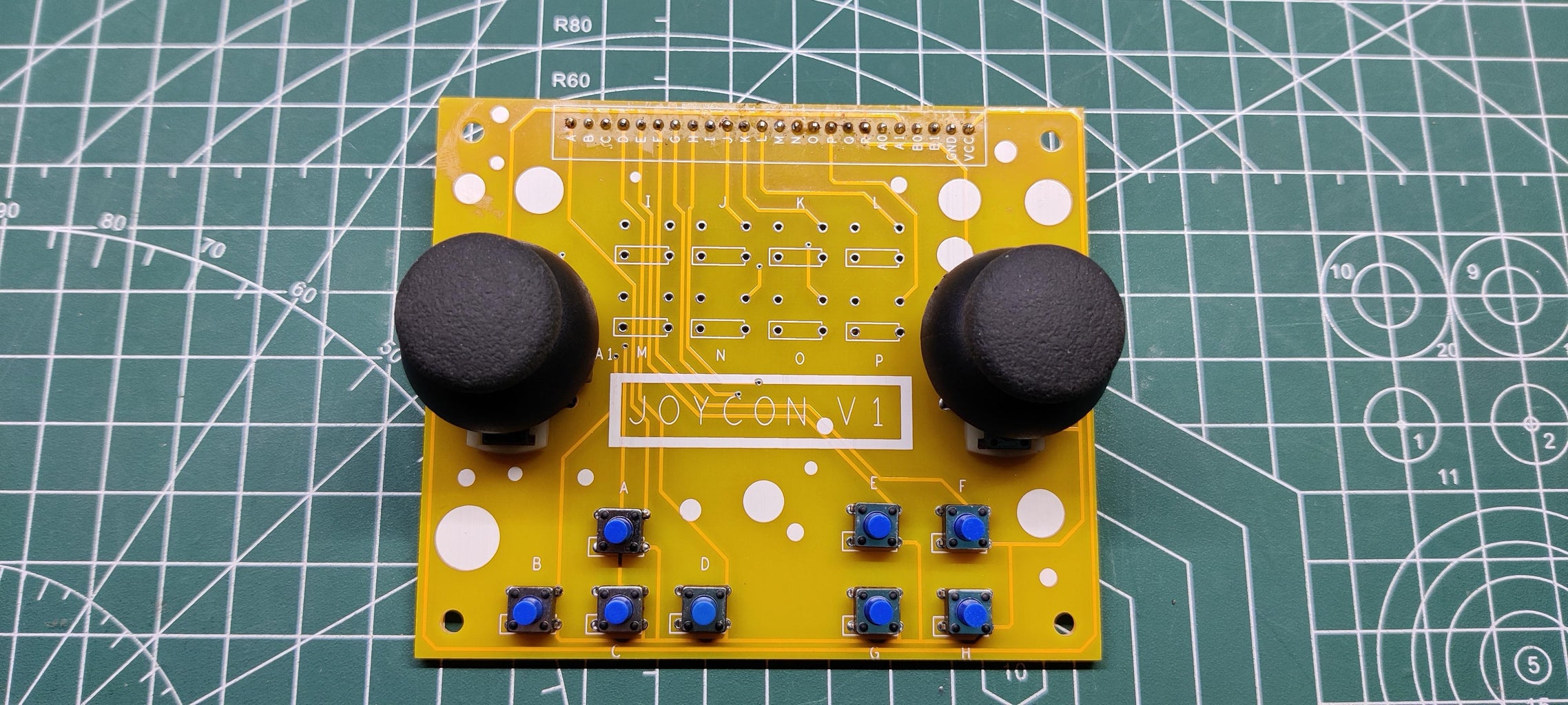
The Joycon Board is a straightforward PCB that acts as a breakout board for buttons and analog sticks.
Each button is wired to the header pin and GND and works in a pull-down configuration. Also, the analog pins of the joystick are connected with both VCC and GND, and the middle pin of all potentiometers is connected with header pins as well.
A 24-pin header connector, which will be used to mount this board on a breadboard, connects each button.
This board's design is also straightforward, with four buttons on the left D-pad, four on the right D-pad, and the other eight buttons located in the center.
Additionally, two analog joysticks are positioned on the board's left and right sides, just above the D-Pad.
Step 2: PCBWAY


I finished the PCB design and exported the Gerber data, which I then forwarded to PCBWAY for samples.
A PCB order for yellow soldermask with white silkscreen was placed.
PCBs arrived in a week, which was quite quick.
As for the quality of the PCBs, each PCB was produced properly, and there were no faults or misprints anywhere.
Step 3: Board Assembly


- To begin assembling the board, we first install each button and analog stick individually on the PCB
- Then we flip the board over and use a soldering iron to connect the pads of all the buttons.
- We attach a header pin connector to the bottom side before flipping the board once more.
- Using a soldering iron, we solder the header pin pads on the board's top side.
- At last, we add Analog Joystick Thumb Cover to both joysticks.
Step 4: RESULT of Board Assembly

This is what came about once the board was put together.
We can utilize this configuration to control things like a servo motor or create a game controller.
Step 5: Testing


Considering that this board is a button breakout board, we can use it to control LEDs or even read button presses.
#include <Servo.h>

Servo myservo;  // create servo object to control a servo

int potpin = A0;  // analog pin used to connect the potentiometer
int val;    // variable to read the value from the analog pin

void setup() {
  myservo.attach(6);  // attaches the servo on pin 9 to the servo object
}

void loop() {
  val = analogRead(potpin);            // reads the value of the potentiometer (value between 0 and 1023)
  val = map(val, 0, 1023, 0, 180);     // scale it to use it with the servo (value between 0 and 180)
  myservo.write(val);                  // sets the servo position according to the scaled value
  delay(15);                           // waits for the servo to get there
}
By reading the joystick's pot value and adjusting the servo position in accordance with it, we can even use joysticks to drive servo motors.
Step 6: Game Controller Implementation- ESP32 Game Controller


Here's an awesome way of using this board: making a wireless game controller by using an ESP32 development board and some jumper wires.
In accordance with the circuit shown above, we connect the ESP32 to every pin on the Joycon.
There are a total of 12 buttons used, including 2 analog stick buttons and 10 regular buttons.
Additionally, 3.3V and GND are connected to VCC and GND, respectively, to power the analog stick potentiometers.
Step 7: Code
Here's the code that I have used.
#include <BleGamepad.h>
#include <FastLED.h>

CRGB leds[13];
BleGamepad bleGamepad("ESP Controller", "ElectroPoint4u", 100);

// TRIGGER BUTTONS
#define LT 2
#define RT 23

// LEFT-JOYSTICK
#define LH 34
#define LV 35
#define LS 15

// RIGHT-JOYSTICK
#define RH 22    //39
#define RV 0     //36
#define RS 19

// D-PAD
#define L1 32
#define L2 33
#define L3 27
#define L4 14

#define R1 18
#define R2 5
#define R3 17
#define R4 16

// BATTERY VOLTAGE
#define ADC 4

// NEOPIXEL
#define DATA_PIN 13

// PERIFERALS
//  #define MIC 25
//  #define SPEAKER 26

int buttons[8] = {32, 33, 27, 14, 18, 5, 17, 16};

int period = 1000;
unsigned long time_now = 0;

const int numberOfPotSamples = 5;     // Number of pot samples to take (to smooth the values)
const int delayBetweenSamples = 2;    // Delay in milliseconds between pot samples
const int delayBetweenHIDReports = 5; // Additional delay in milliseconds between HID reports
const int debounceDelay = 10;        // Delay in milliseconds between button press

int previousButton1State = HIGH;
int previousButton2State = HIGH;
int previousButton3State = HIGH;
int previousButton4State = HIGH;

void setup() {
  Serial.begin(115200);
  FastLED.addLeds<NEOPIXEL, DATA_PIN>(leds, 6);
  FastLED.setBrightness(64);
  for (int i = 0; i < 8; i++) {
    pinMode(buttons[i], INPUT_PULLUP);
  }
  pinMode(LT, INPUT_PULLUP);
  pinMode(RT, INPUT_PULLUP);
  pinMode(LS, INPUT_PULLUP);
  pinMode(RS, INPUT_PULLUP);
  bleGamepad.begin();
  Serial.println("Starting BLE work!");

  leds[0] = CRGB::Blue;
  leds[5] = CRGB::Blue;
  FastLED.show();
  delay(200);
  leds[1] = CRGB::Blue;
  leds[4] = CRGB::Blue;
  FastLED.show();
  delay(300);
  leds[2] = CRGB::Blue;
  leds[3] = CRGB::Blue;
  FastLED.show();
  delay(1000);
  FastLED.clear();
  FastLED.show();
}

void loop() {
  if (bleGamepad.isConnected()) {
    for (int i = 0; i < 6; i++) {
      leds[i] = CHSV( HUE_GREEN, 255, 64);
    }
    FastLED.show();
    while (millis() > time_now + period) {
      Serial.println("Checking Battery Level");
      batteryLevel();
      time_now = millis();
    }
    int currentButton1State = digitalRead(R1);
    int currentButton2State = digitalRead(R2);
    int currentButton3State = digitalRead(R3);
    int currentButton4State = digitalRead(R4);

    if (currentButton1State != previousButton1State) {
      if (currentButton1State == LOW)
        bleGamepad.press(BUTTON_5);
      else
        bleGamepad.release(BUTTON_5);
    }
    previousButton1State = currentButton1State;

    if (currentButton2State != previousButton2State) {
      if (currentButton2State == LOW)
        bleGamepad.press(BUTTON_2);
      else
        bleGamepad.release(BUTTON_2);
    }
    previousButton2State = currentButton2State;

    if (currentButton3State != previousButton3State) {
      if (currentButton3State == LOW)
        bleGamepad.press(BUTTON_1);
      else
        bleGamepad.release(BUTTON_1);
    }
    previousButton3State = currentButton3State;

    if (currentButton4State != previousButton4State) {
      if (currentButton4State == LOW)
        bleGamepad.press(BUTTON_4);
      else
        bleGamepad.release(BUTTON_4);
    }
    previousButton4State = currentButton4State;

    if (digitalRead(LS) == LOW) {
      Serial.println("Left Joystick");
      bleGamepad.press(BUTTON_6);
      delay(debounceDelay);
      bleGamepad.release(BUTTON_6);
    }
    if (digitalRead(RS) == LOW) {
      Serial.println("Right Joystick");
      bleGamepad.press(BUTTON_3);
      delay(debounceDelay);
      bleGamepad.release(BUTTON_3);
    }

    if (digitalRead(LT) == HIGH) {
      Serial.println("Left trigger");
      bleGamepad.press(BUTTON_7);
      delay(debounceDelay);
      bleGamepad.release(BUTTON_7);
    }
    if (digitalRead(RT) == LOW) {
      Serial.println("Right trigger");
      bleGamepad.press(BUTTON_8);
      delay(debounceDelay);
      bleGamepad.release(BUTTON_8);
    }

    int potValues[numberOfPotSamples];
    for (int i = 0 ; i < numberOfPotSamples ; i++) {
      potValues[i] = analogRead(LH);
      delay(delayBetweenSamples);
    }
    int potValue = 0;
    for (int i = 0 ; i < numberOfPotSamples ; i++) {
      potValue += potValues[i];
    }
    potValue = potValue / numberOfPotSamples;
    int adjustedValue = map(potValue, 0, 4095, 127, -127);


    int potValues2[numberOfPotSamples];
    for (int i = 0 ; i < numberOfPotSamples ; i++) {
      potValues2[i] = analogRead(LV);
      delay(delayBetweenSamples);
    }
    int potValue2 = 0;
    for (int i = 0 ; i < numberOfPotSamples ; i++) {
      potValue2 += potValues2[i];
    }
    potValue2 = potValue2 / numberOfPotSamples;
    int adjustedValue2 = map(potValue2, 0, 4095, 127, -127);


    int potValues3[numberOfPotSamples];
    for (int i = 0 ; i < numberOfPotSamples ; i++) {
      potValues3[i] = analogRead(RH);
      delay(delayBetweenSamples);
    }
    int potValue3 = 0;
    for (int i = 0 ; i < numberOfPotSamples ; i++) {
      potValue3 += potValues3[i];
    }
    potValue3 = potValue3 / numberOfPotSamples;
    int adjustedValue3 = map(potValue3, 0, 4095, 255, 0);


    int potValues4[numberOfPotSamples];
    for (int i = 0 ; i < numberOfPotSamples ; i++) {
      potValues4[i] = analogRead(RV);
      delay(delayBetweenSamples);
    }
    int potValue4 = 0;
    for (int i = 0 ; i < numberOfPotSamples ; i++) {
      potValue4 += potValues4[i];
    }
    potValue4 = potValue4 / numberOfPotSamples;
    int adjustedValue4 = map(potValue4, 0, 4095, 255, 0);
    /*
      Serial.print(adjustedValue);
      Serial.print(" || ");
      Serial.print(adjustedValue2);
      Serial.print(" || ");
      Serial.print(adjustedValue3);
      Serial.print(" || ");
      Serial.println(adjustedValue4);
    */
    bleGamepad.setAxes(adjustedValue, adjustedValue2, 0, 0, adjustedValue3, adjustedValue4, DPAD_CENTERED);
    delay(delayBetweenHIDReports);

    if (digitalRead(L1) == LOW)
      bleGamepad.setAxes(adjustedValue, adjustedValue2, 0, 0, adjustedValue3, adjustedValue4, DPAD_UP);
    if (digitalRead(L2) == LOW)
      bleGamepad.setAxes(adjustedValue, adjustedValue2, 0, 0, adjustedValue3, adjustedValue4, DPAD_LEFT);
    if (digitalRead(L3) == LOW)
      bleGamepad.setAxes(adjustedValue, adjustedValue2, 0, 0, adjustedValue3, adjustedValue4, DPAD_DOWN);
    if (digitalRead(L4) == LOW)
      bleGamepad.setAxes(adjustedValue, adjustedValue2, 0, 0, adjustedValue3, adjustedValue4, DPAD_RIGHT);
  }
}

void batteryLevel() {
  int sensorValue = analogRead(ADC);
  float voltage = sensorValue * (5.12 / 4095.0);
  Serial.print(voltage);
  Serial.print("V ||");
  int percentage = (voltage / 4.2) * 100;
  Serial.print(percentage);
  Serial.println("%");
  bleGamepad.setBatteryLevel(percentage);
  if (percentage < 60) {
    Serial.println("LOW battery");
    for (uint8_t i = 30; i < 220; i++) {
      for (int j = 0; j < 6; j++) {
        leds[j] = CHSV( HUE_RED, 255, i);
      }
      FastLED.show();
      delay(15);
    }
    for (uint8_t i = 220; i > 30; i--) {
      for (int j = 0; j < 6; j++) {
        leds[j] = CHSV( HUE_RED, 255, i);
      }
      FastLED.show();
      delay(15);
    }
  }
}
This code was partially borrowed from the Electropoint ESP32 Game Controller project code, which makes use of the ESP32-BLE-Gamepad Library created by lemmingDev.
https://github.com/lemmingDev/ESP32-BLE-Gamepad
It's available on Github, and you need to install it before using this sketch.
Step 8: Result


The game is currently being played through Bluetooth with a game controller.
We must supply this controller with 5V of power in order to connect to it.
Once the ESP CONTROLLER is connected to our smartphone through Bluetooth, we can load any game that accepts controller input and have it function immediately.
There are some problems with this controller that can be fixed by making a small change to the code, which is a project for later.
This is it for today, folks. Leave a comment if you need any help regarding this project.
Special thanks to PCBWAY for supporting this project, do check them out for great PCB Service at a lower cost.
Peace out

Participated in the
Anything Goes Contest


![Tim's Mechanical Spider Leg [LU9685-20CU]](https://content.instructables.com/FFB/5R4I/LVKZ6G6R/FFB5R4ILVKZ6G6R.png?auto=webp&crop=1.2%3A1&frame=1&width=306)


