Introduction: Laser Center Finder. (drill Press and Mill)


Easily and quickly find the center of anything on the drill press or mill table.
Sure you can use the old method, measure, divide by two and mark and centerpunch, however that wont work with a hole, try marking the center of a hole with a red fineliner. :)
Finding the center of a hole is not as some might think, a machinists zen problem, frequently in the garage I have needed to make a 13mm (max capacity of my drill press) much larger, like 25mm.
Without the laser center finder you would need to chuck a 13mm rod in the press or mill to zero the existing cavity and swop out tooling to make it larger, the process can be made faster with a laser center finder.
I was looking for a method of boring a 18mm dia hole in a block of resin using a mill and happened upon a laser center finder on the Gadgetbuilders site.
http://www.gadgetbuilder.com/LaserCenterFinder.html
My ears perked up at the mention of "for mill and drill press" as I have been in the situation where you need to drill a hole centered on a block and expect to have many more instances in the future.
After watching the Dan Gelbart video regarding its uses, I had a new task on the No1 spot on my DIY list.
Dan Gelbart's prototyping, fast forward to 2:20, when he starts discussing the center finder's uses.
Step 1: Construction.


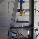
I used a 8mm steel bar from an old printer, nice thing is that it has threaded ends and presence of mind at the time meant that I attached the screws once I had removed the bars, always a win.
The bar has a 4.7mm dia shoulder at each end which worked out well, a 8mm hole in the top of a 25mm sq tube with a 4.5mm hole in the bottom and a 8cm length of bar had a new purpose in my garage.
I used Q-bond with the metal grey filler powder to lock things in place, both topside and underneath on the screw, same method was used to mount the laser.
A small cheap red 1mw laser pointer was mounted at an angle and cable tied temporarily to prevent it sliding out under centrifugal forces. A bit of bent perspex holds the switch on in use.
The cutouts and angled end were to try and balance out the mild vibration, it initially occurred at 1000 rpm and afterwards it was noticable at 2200 rpm, bearing in mind the full circle is visible at 800 rpm, which is probably a good working speed.
The final version with the milled cutouts has very minor vibration at the 2500 max rpm of my drill press, but like I mentioned earlier, 800 to 1000 rpm is a good working speed.
Step 2: Uses.


It works well in practice, as can be seen on this scrap block, the open circle is obviously due to shutter speed in low light.
Its easy enough getting a bar or cylinder centered, make sure the V's near the edge are equal left and right.
When centering a hole, look for a horizontal beam on the inside wall to know when its centered.
Step 3: Last Thoughts


In the drill press, my focal point is about 10cm below the laser due to me using a 70 degree angle mount instead of 45 degrees.
I figured the steeper angle would mean less tendency of the laser to climb out of the mounting due to centrifugal forces and as an added bonus, the rate of change of the circles diameter is more gradual (finer control) when moving the quill up and down than it would have been with a 45 degree mount.
The red laser is very dim on certain materials and a green laser would be better, although I dont think they make them in this size.
The main priorities when making the center finder are getting the shaft perpendicular and centered. The laser should also be on the centerline of the square tube so that its beam hits the drilling axis, although the inclined laser angle isnt critical.