

Introduction: Laser Line Material Aligner for Laser Cutting Machine


I have a small DIY Laser engraver/Cutting machine which operates on GRBL Code.
I don't have a square stack on base to identify where the material is exactly parallel to Axis.
Sometimes because of a normal misalignment boundary line going out and it mis - engrave on board and that piece is a waste for me.
For saving money, material and time I made this project .
This laser Guider helps me to place material as per square of the machine axis and machine engrave it very well.
This project saves money as well as machining time by guiding through LASER.
Let’s make this Instructable & Save Money!!
ATTRIBUTION
I use Idea of LASER line conversation from @daxpatel from His project $15 DIY Adjustable Line Laser Alignment Tool .
Thanks for idea @daxpatel.
Supplies


- Laser Diods x 2 (Buy Extra 2 piece if any diod run out)
- Round Glass Rod
- Laptop for design (Not necessary, if you use my design)
- 3D Printer Access
- Soldering Iron & Solder Wire
- Some wires and 5V 1A Adaptor for Power supply.
Step 1: Measure Dimensions

- I have a small DIY laser Machine for engraving on MDF and Acrylic material. Laser Diod Rating is 2.5W and Input is 12v 2A.
- Dimension of outer casing is 42x42mm and Laser diode lens diameter is 16mm.
- Our Purchased Laser diod size is 6.1mm in diameter.
- Glass Rod diameter is 7.2mm in diameter.
- We need to cut a glass rod 20mm in length.
Step 2: Laser Dot to Laser Line Converter

- Laser diode Emmitt Dot Laser .But we need a line of laser for alignment of Material on Laser engraving Bed.
- For conversion in Line laser, we use internal optical reflection inside glass Rod. Dot line pass through Cylindrical rod and it convert into line laser by law of internal reflection.
- For testing and Simulation of Light through a glass cylinder ,I use a Light simulator for testing purposes.
- Checkout the link below for Light simulator and create your own Line laser as per your need.
https://ricktu288.github.io/ray-optics/simulator/
In the simulator Light source is a beam light and uses a circular glass medium for internal reflection and gives the result in a Linear line on the wall.
IMAGE COURTESY: @daxpatel
Step 3: Testing Our Simulation in the Real World.

I Purchase Glass sterile rod from amazon to use as an internal reflection cylinder.
Also purchased a 5mw power Laser from amazon. I cut a glass rod in 20mm Piece and connected a laser diode with a 5v 0.3mw power adapter to start the Laser.
I Just move Laser diode at tangent of glass rod Cylindrical surface.
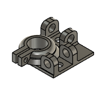
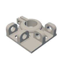
Step 4: Design Laser Holder in Fusion360


After successful testing of our theory of internal reflection, I started to make Design of Set square which is attached to a laser diode.
Diameter of the laser diode head is 16.5mm.
We start with a plane 50x50mm and place 16.5mm diameter inside.
We need to place a laser and glass around the circular hole at 90 degrees of angle.
For placing the glass rod I make 2 rectangle parts 10x5mm 12mm apart and extrude it 12mm .
Same rectangle placed at 90 degrees around the circle.
Make a 7mm hole in both rectangles to fit the glass rod inside.
Make hole for the laser diode placing exactly down to the glass.
Export design as STL file for 3d print.
Step 5: 3D Print Design


Use Appropriate slicer software to make a .GCODE file for a 3d printer.
I use Ender-3 for 3d printing and CURA as a slicer program.
Use the below Printing setting for good Print.
Layer height : 0.2mm
Wall thickness : 2
Infill; 20 %
Support;: yes
Builtplate adhesion : Brim/Skirt.
Speed : 55mm/s
Material : PLA/ABS
Nozzle temperature: as per material
Bed temperature: as per material
Step 6: Testing Part.


After 3d print ,we place Laser diode and Glass rod inside the 3d printed part as per design.
Connect the Power supply with both lasers.
Lasers pass through the Glass rod and Reflect line on the wall.
We use both lasers at 90 degrees to make cross using lasers on the wall. Now, we attach this module on the laser engraver head.

Participated in the
Laser Challenge


