Introduction: Leaf It to Me!

As a group of full time students with busy schedules and frequent unpredictable travel and obligations, one thing that often gets overlooked is care for our household plants. A lot of young professionals in careers like consulting also face the same issue while they’re traveling on consulting assignments for a major part of the week. Even if students and professionals are at home, they might occasionally forget to water their plants due to their busy schedules, or worse, over- or under-water their plants. We decided to create a plant watering system that was automatic, aesthetically pleasing, and allowed us to travel with peace of mind that our plants were well cared for.
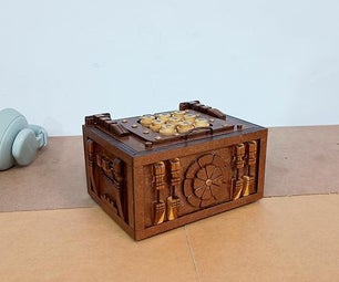
It was important to us that this system would work for a variety of plants - including ones that need to be watered daily or ones that would be watered weekly. The system would need to stand alone, on a shelf or tabletop similar to where one would put a plant. We crafted the system with a typical house plant in mind, but created three “settings” based on plant watering frequency. We wanted our system to look nice, since it is supposed to be home decor. This is why we decided to use lights to indicate when it was being watered and 3D printed leaves to indicate what setting was being used.
Overall, our “Leaf it to Me” plant watering system is perfect for a student or busy professional on the go, and can add a nice touch to any home while ensuring that plants don’t go thirsty!
Note: This project is based on https://www.instructables.com/id/Automatically-wa... but extends the design to include a lamp and adjustable timer knob.
Supplies
- Arduino Uno with USB cable (http://adafru.it/50 and http://adafru.it/62)
- Breadboard (http://adafru.it/64) 1N4001 diode (http://adafru.it/755)
- PN2222A and 2N3904 transistors (http://adafru.it/756 and https://www.amazon.com/General-Purpose-Transistor-2N3904-NPN/dp/B004J5ZWEQ)
- 12V 1A power supply (http://adafru.it/798)
- Peristaltic pump (http://adafru.it/1150)
- Alligator clips (http://adafru.it/1008)
- 5V LED lamp (can get lamp and tank from https://smile.amazon.com/YCTECH-Gallon-Aquarium-Starter-220white/dp/B07Y9MMD1D/ref=sr_1_4?keywords=aquarium&qid=1574190755&sr=8-4)
- Small LED (optional but useful for testing)
- Water tank
- Potentiometer (https://www.amazon.com/DIKAVS-10PCS-Breadboard-Potentiometer-Arduino/dp/B01GVD7FRU)
- Resistors (220 and 235 ohms, although exact value probably not too important)
- Jumper wires for breadboard
- Acrylic (for electronics shelf)
- Wooden boards (for base)
- PLA filament (for 3D printed angle brackets)
- Metal angle brackets
Step 1: Construct Circuits

On the breadboard, construct the three circuits (shown in the diagrams) that will connect to the pump, lamp, and potentiometer.
The circled values (13, A0, A1) refer to pins on the Arduino. Since the motor is large and the potentiometer (control knob) may need to be physically separated from the rest of the circuitry, it is advisable to use the alligator clips to attach the motor and a long set of jumper wires to attach the potentiometer.
Note that there is only one 5V pin on the Arduino, so it will be necessary for this pin to connect to both the potentiometer and the lamp.
Explanation: The transistors act as electronic switches. If a small current flows from base (middle pin) to emitter (bottom pin), then a large current is allowed to flow from collector (top pin) to emitter. This allows a small control current (such as can be produced by Arduino pins A1 and 13, with a maximum output of 40 mA) to control much larger current flows (the outputs of 5V and Vin, which have no inherent control mechanism but can allow draws of 400 mA or more).
The motor can be modeled as a resistor and inductor in series, but for physically constructing the circuit it is only a single unit. Due to the inductance, a large negative voltage differential will briefly build up across the motor if current is suddenly switched off, which could damage the motor and/or the Arduino. To avoid this, we add a reverse biased diode across the motor to discharge this excess voltage.
Step 2: Program Arduino


Connect the Arduino to a computer using the USB cable and upload the following piece of code:
<p>long sensorPin = A0;    // select the input pin for the potentiometer<br>long motorPin = A1;      // select the pin for the motor
long lightPin = 13;
long sensorValue = 0;  // variable to store the value coming from the sensor</p><p>long dayLength = 20000; // 20 seconds for testing</p><p>long lightOnTime = dayLength/2;
long lightOffTime = dayLength - lightOnTime;</p><p>long motorOnTime = 5000;
long motorOffTime = dayLength - motorOnTime; // until set otherwise</p><p>// timers
long lightTimer, motorTimer;</p><p>bool motorOn, lightOn;</p><p>void turnMotorOff();
void turnMotorOn();
void turnLightOff();
void turnLightOn();</p><p>void setup() {
  pinMode(motorPin, OUTPUT);
  pinMode(lightPin, OUTPUT);</p><p>  // begin with light off and motor off
  turnMotorOff();
  turnLightOff();</p><p>  // longialize timers
  lightTimer = lightOffTime;
  motorTimer = motorOffTime;
}</p><p>void loop() {
  long waitTime = min(motorTimer, lightTimer);
  delay(waitTime);
  motorTimer -= waitTime;
  lightTimer -= waitTime;
  if (motorTimer < lightTimer){
    // take motor action
    if (motorOn) {
      turnMotorOff();
      motorTimer = motorOffTime;
    }
    else {
      turnMotorOn();
      motorTimer = motorOnTime;
    }
  }
  else {
    // take light action
    if (lightOn) {
      turnLightOff();
      lightTimer = lightOffTime;
    }
    else {
      turnLightOn();
      lightTimer = lightOnTime;
    }
  }
}</p><p>void turnMotorOn() {
  digitalWrite(motorPin, HIGH);
  motorOn = true;
}</p><p>void turnMotorOff() {
  digitalWrite(motorPin, LOW);
  motorOn = false;
  sensorValue = analogRead(sensorPin);
  motorOffTime = (long)(dayLength/2*exp((float)sensorValue * log(4)/1023)) - motorOnTime;
}</p><p>void turnLightOn() {
  digitalWrite(lightPin, HIGH);
  lightOn = true;
}</p><p>void turnLightOff() {
  digitalWrite(lightPin, LOW);
  lightOn = false;
}</p>
You should now see the lamp turn on and off every 10 seconds and the LED connected to the motor turn on for 5 seconds and turn off with a frequency determined by the potentiometer setting. The motor will not run yet since the voltage provided by the USB (5V) is insufficient for the pump.
The values for dayLength and motorOnTime are set to small values for testing. When everything is working correctly, set dayLength = 86400000 and motorOnTime to be 50000 (for delivering ¼ cup of water at a time for the pump listed) or, in general, the amount of watering time (in milliseconds; the pump listed delivers about 1 mL/sec).
Explanation: The code is somewhat complicated since the Arduino Uno only has a single delay timer but must control two different cycles with different periods. The loop() function basically determines which event will happen soonest and performs that one, adjusting the timers accordingly.
At the end of a pump cycle, after turning the motor off, the Arduino reads the input from the potentiometer (pin A0) to determine the amount of time to delay before the pump is reactivated, ranging from half a day to two days. It does this by reading in the voltage from the control pin of the potentiometer, which ranges from 0 to 5 V depending on where the dial is turned, and mapping this to a time scale in the desired range.
Step 3: Power the Arduino
Unplug the USB cable from the computer, and, after the cable is disconnected (to avoid potentially damaging the computer), connect the Arduino to the 12V adaptor. The circuit should work as before except that now the pump should also operate. (This should be visible or perceptible to the touch even if no water is connected.)
Step 4: Create Openings in Back Board for Two Tubes, Potentiometer and Angle Brackets
The supporting frame consists of two 12 in X 12 in wooden boards for the base and side. Using a laser cutter, create three small openings towards the top of the wooden side board, large enough for the water drawing tube, the water dispensing tube, and the control potentiometer respectively. At the desired height of the electronics shelf, make two holes (using a drill press) for screws for the metal angle brackets supporting the shelf.
Step 5: Laser Cut Electronics Shelf and Leaves

The electronics (breadboard, Arduino, motor) will be attached to a shelf at the back of the side wooden board. Using a laser cutter, cut a 12 in long rectangular piece of acrylic that is wide enough to comfortably attach the electronics. Make two holes (for screws) the same distance apart as the screw holes in the side board above. Laser cut three leaves of increasing size to use as indicators of watering frequency.
Step 6: 3D Print Angle Brackets

The side wooden board will be affixed to the base board with 3D printed angle brackets. The CAD file can be found here: https://www.thingiverse.com/thing:2226. Print four of these angle brackets.
Step 7: Assembly and Attachment


Using a drill press, make two holes near the bottom of the base wooden board, where the side of the 3D printed angle brackets will be screwed in. Position the side wooden board perpendicularly an angle-bracket-distance away from one edge of the base board. Hot glue the four 3D printed angle brackets in place in opposing pairs, two on each side of the side board, such that a single screw and nut can be inserted to fasten two angle brackets at once. Once the four brackets have been screwed into the side board, attach the acrylic electronics shelf to the side board with screws and nuts. Insert the tubes from the pump through the holes in the side board such that they protrude out to the front of the setup. Fix the potentiometer with hot glue in its hole in the side board such that the control dial protrudes out to the front. Using velcro and tape as needed, affix the breadboard, Arduino, and motor to the shelf. Fill the water tank and place it on the base board next to the plant. Place the water drawing tube in the tank and the water dispensing tube in the plant pot. Affix the three leaves around the potentiometer at the front of the side board according to size to indicate the direction of rotation from low to high frequency.
Step 8: Final Operation
We wanted to make sure that there was sufficient distance/separation between any electrical equipment and water in our setup. For this reason, all of the circuitry and electronics are behind the vertical wooden board on an acrylic shelf. The plant is watered at fixed time intervals, as determined by our arduino code. The LED light turns on for 12 hours a day (for the demo video, 1 day = 20 seconds). Frequency of watering the plant can be adjusted (using the potentiometer) from 0.5-2 times a day.