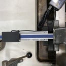
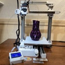
Introduction: Linear Screw Double Rail
The original screw driven rail lends itself nicely to having one of each on each side of a 3D printer. Up and down is accurate but BY itself, it doesn’t have a lot of lateral support.
Since I’m looking into cantilever designs, I revised the rail to introduce a second linear rod, widening and thus stabilizing the linear screw. I intend to use this implementation in a revamp of my Cantilever printer
I'm a big fan of Auto bed leveling so I did not design the End-stop as an integrated component but instead went with a detachable End Stop incorporating a much smaller micro switch
STL files are included with the Instructable but if you want to download the entire model you can do this on GrabCad.com: https://grabcad.com/library/lead-screw-driven-linear-rail-double-1
Step 1: Parts
There are 3 printed components to this rail (4 if you count the optional End Stop Case). The STL files are included. You can print using PLA (0.2mm 15% infill). All fittings are tight, so each 3D printer may need a little scaling tests.
following components can all be found on Amazon.com but if you have time and patience you can possibly source many from AliExpress.com for less.
Flexible Shaft Couplings 5mm to 8mm: http://amzn.to/2yYJ9TJ
2-Pack - Linear Motion Rod 8 mm x 406mm Shaft: http://amzn.to/2yYJ9TJ
micro switch: http://amzn.to/2DAfRxS
1010 72 inches (8020 inc.): http://amzn.to/2yYJ9TJ
nema 17 1.7A (5 pack): http://amzn.to/2yYJ9TJ
SCS8UU Linear Motion Ball Bearing: http://amzn.to/2yYJ9TJ
M4 8mm: http://amzn.to/2CMkRyN
m3 10mm: http://amzn.to/2CMkRyN
Lead Screw 8mm: http://amzn.to/2D8pXVY
In case you do not have access to a 3D printer you can purchase the printed parts here:
PLA: https://www.ebay.com/itm/263523950415
PETG: https://www.ebay.com/itm/263523944028
Update 3/15/2018: Per request, I've added the STL files (DoubleScrewRail_2040_STL.zip) for a 2040 extrusion assuming a 2020 cross bar to fit in slider
Update 4/26/2018: I've added the STL files for 12mm Rods as they appear to offer much more stablility
SCS12UU Linear Motion Ball Bearing (2x) $16.40 https://amzn.to/2I0NwDY
Linear Motion Rod 12 mm x 400mm Shaft (2x) $25.74 www.mcmaster.com (+shipping)
Step 2: Assembly
Like with the original Linear Screw Rail, All components were specifically designed for the 1010 aluminum extrusion WITH grooves. The attached picture shows the connections are strong. Holes have been added to the components to screw it on using a t-nut (I'v seen no need for that).
All components couple to the extrusion side ways (no caps). This allows for moving it for best position based on your use.
The lips on the Carriage are similar to the lips that clamp it's own components to the rail. This allows you to insert 1010 extrusion perpendicular to this rail. There are two holes with room between the SCSUU blocks for screws and possible t-nuts.
This Axis was used for the C3Dt/c Printer, and below is the assembly video created for this axis:
Step 3: Testing
I use the marlin software and a bare RAMPS 1.4 that is controller via pronterface
I use Marlin 1.1.x to test and have the screw rail connected to the Z-axis In the Marlin configuration.h file make sure you set the proper length for the screw rail // Travel limits after homing (units are in mm)
Based on the length of the screw rail, rails lost in coupler and end end connector and the height of the carriage, the range for travel is 0 to 290mm. Not setting the Z_MAZ_POS in the configuration may damage the rail as it would try to travel beyond it's capacity.
#define X_MIN_POS 0
#define Y_MIN_POS 0
#define Z_MIN_POS 0<br>#define X_MAX_POS 200<br>#define Y_MAX_POS 200<br>#define Z_MAX_POS 290
The Lead screw is 2mm pitch 4 start. For Marlin \thist comes to 400 steps/mm
#define DEFAULT_AXIS_STEPS_PER_UNIT { 80.08748,80.08748,400,456 }<br>If you liked this check out my other instructables or visit my website at https://core3d.tech
Step 4: Parts at Work
In case you're wondering what you can do with this component check out this video

Participated in the
Epilog Challenge 9


