Introduction: Linear Screw Rail
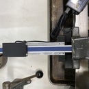
As a continuation on the the Generic Linear Actuator this screw rail uses similar conntectors but is screw driven as opposed to belt driven. A linear rail like this one would be more suitable slower motion (like a Z-axis).
This design comes both with a built-in End-stop and without.
The design was created in Fusion 360 and can be downloaded from GrabCad.com
The linear rail incorporates the following 3rd party models
https://grabcad.com/library/pillowblock-8mm-sc8uu-...
Step 1: Parts
following components can all be found on Amazon.com but if you have time and patience you can possibly source many from AlieExpress for less.
Flexible Shaft Couplings 5mm to 8mm http://amzn.to/2AZiVlZ
2-Pack - Linear Motion Rod 8 mm x 406mm Shaft http://amzn.to/2B12hCl
end-stops http://amzn.to/2B12hCl
1010 72 inches (8020 inc.) http://amzn.to/2B12hCl
threaded rod 5/16-18 http://amzn.to/2B12hCl
nut (100 pack) http://amzn.to/2B12hCl
nema 17 1.7A (5 pack) http://amzn.to/2B12hCl
SCS8UU Linear Motion Ball Bearing http://amzn.to/2B12hCl
m4 8mm http://amzn.to/2B12hCl
m3 10mm http://amzn.to/2B12hCl
square nut http://amzn.to/2Dpxxg0
Pan head screw (30mm) http://amzn.to/2BLd2tC
if you choose to go with the more accurate 8mm lead screw, I use this one: http://amzn.to/2l7z69V
If this setup would be part of the Z-Axis on a 3D printer you can probably opt for a less strong Nema 17 (and cheaper) as the Z-axis tends to need less.
Threaded Rod and nuts of course can be found at your local hardware store. If you want the extrusion to be cut to length, I suggest you order them directly from the 8020.net Ordering pre-cut should make for better 90 degree angle cuts.
If you do not have access to a 3D printer I can provide you with the 3D printed parts through EBay: https://www.ebay.com/itm/263524092786
Step 2: Assembly
All components were specifically designed for the 1010 aluminum extrusion WITH grooves. It may seem like clipping it on may not suffice but if you look at the attached picture you'll see it is strong. I did add holes to the components to screw it on using a t-nut.
The screw rod is 5/16 18 where as, the flexible coupler is metric (8mm). You may want o add some tape around the rod prior to inserting into coupler.
All components couple to the extrusion side ways (no caps). This allows for moving it for best position based on your use.
The End-stop casing requires electric plug prior to inserting.
The 30mm pan head screw goes into the wheel for the adjustable end-stop. The fit is tight. I recommend temporarily adding nut when inserting into wheel and forcing it all the way in. After that remove the nut.
Step 3: Testing
I use the marlin software and a bare RAMPS 1.4 that is controller via pronterface
I use Marlin 1.1.x to test and have the screw rail connected to the Z-axis
In the Marlin configuration.h file make sure you set the proper length for the screw rail
// Travel limits after homing (units are in mm)<br>#define X_MIN_POS 0
#define Y_MIN_POS 0
#define Z_MIN_POS 0<br>#define X_MAX_POS 200<br>#define Y_MAX_POS 200<br>#define Z_MAX_POS 300
Since I'm using the 5/16th screw rod I need to set the steps per mm for this particular rod.
A good calculator for this can be found at https://www.prusaprinters.org/calculator/
In the case of my stepper motor, stepping and 5/16 screw it comes to 2267.72 steps/mm
#define DEFAULT_AXIS_STEPS_PER_UNIT { 80, 80, 2267.72, 92.6}If you are using the more accurate Lead screw with 2mm spacing, it comes to 400 steps/mm
#define DEFAULT_AXIS_STEPS_PER_UNIT { 80.08748,80.08748,400,456 }Step 4: Files
The actual model for this linear rail was created in Fusion 360 and can be found at Grabcad.com https://grabcad.com/library/screw-driven-rail-1
The STL files for all the 3D printable components are available in this instructable. It has both the stl files for Nema end with and without Endstop and the slider for both simply screw rod (with bolt) and the more accurate lead screw.
All components have an extremely tight fit on the aluminum extrusion. Since all 3D printer are not created equal, try out the end clamp first (least filament) for a good fit.
If you liked this check out my other instructables or visit my website at https://core3d.tech
If you want to implement this using 2020 extrusion I have the STLs attached for the rail (without endstop). I have not been able to upload a zip file recently so I've added the 6 files for use with 2020 extrusion


