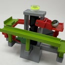
Introduction: Marblevator, Emoji.
It's difficult to determine whether this animated "Marblevator, Emoji" emoji has "telekinetic powers" or is just amazed at the apparent physics defying properties of the marble track. In any case, the grandkids enjoyed it and that makes my very happy!
As usual, I probably forgot a file or two or who knows what else, so if you have any questions, please do not hesitate to ask as I do make plenty of mistakes.
Designed using Autodesk Fusion 360, sliced using Ultimaker Cura 4.12.1, and 3D printed in PLA on Ultimaker S5s and an Ultimaker 3e.
Supplies
Soldering iron and solder.
Thick double sided tape.
Thick cyanoacrylate glue.
Step 1: Parts.
I acquired the following parts:
- One motor speed controller : https://www.amazon.com/dp/B07WGT8K82?psc=1&ref=ppx_pop_dt_b_asin_title
- One N20 6VDC 100RPM gear motor.
- One LiPo Battery: https://www.amazon.com/gp/product/B07BTSNKT7/ref=ppx_yo_dt_b_search_asin_title?ie=UTF8&psc=1
- Two wired female JST connectors suitable for the battery connector.
- One wired male JST connector suitable for the female JST connectors.
- One 9.5mm ball bearing.
- Two 6mm diameter by 1.5mm thick neodymium magnets.
I 3D printed the following parts at .06 layer height, 15% infill and no supports:
- One "Arm.stl".
- Four "Bolt (M8 by 8mm).stl".
- One "Cover.stl".
- One "Eyes.3mf" (dual extrusion).
- One "Face.3mf" (dual extrusion).
- One "Mount, Motor.stl".
- One "Retainer, Eyes.stl".
- One "Track Segment 1.stl".
- One "Track Segment 2.stl".
I also have include the 3D printed files "Eyes, Black.stl", "Eyes, White.stl", "Face, Black.stl" and "Face, Yellow.stl" for single extrusion 3D printers.
This is an ultra high precision 3D print and assembly model using at times very small precision 3D printed parts in very tight spaces. Prior to assembly, test fit and trim, file, sand, polish, etc. all parts as necessary for smooth movement of moving surfaces, and tight fit for non moving surfaces. Depending on you printer, your printer settings and the colors you chose, more or less trimming, filing, sanding and/or polishing may be required. Carefully file all edges that contacted the build plate to make absolutely certain that all build plate "ooze" is removed and that all edges are smooth. I used small jewelers files and plenty of patience to perform this step. And polish all moving parts!
The model also uses threaded assembly thus an M8 by 1.25 tap and die will assist with thread cleaning if necessary.
Attachments
Step 2: Assembly.
To assemble the model, I performed the following steps:
- Carefully glued "Track Segment 1.stl" to "Track Segment 2.stl".
- Positioned the slot in "Eyes.3mf" over the pin in "Face.3mf" then secured in place using "Retainer, Eyes.stl" and made certain the eyes slid and rotated in the slot with ease.
- Pressed the face assembly into the track assembly, flush with the track side of the track, then glued in in place.
- Soldered a female JST connector to the gear motor such then when power was applied the motor shaft rotated counter clockwise as viewed from the motor shaft end of the gear motor.
- Pressed the gear motor into "Mount, Motor.stl".
- Pressed two magnets, polarity matching, into "Arm.stl".
- Pressed the arm assembly onto the motor shaft.
- Following the instructions that came with the motor speed controller, prepared the motor speed controller to run on low voltage.
- Attached a female JST connector to the motor speed controller "DC IN" block, red to "+" and black to "-".
- Attached a male JST connector to the motor speed controller "MOTOR" block, red to "+" and black to "-".
- Attached the battery to the top of the motor mount assembly using double sided tape.
- Slid the motor speed controller into "Cover.stl" and loosely secured it in place using the included washer and nut.
- Connected the battery JST connector to the motor speed controller "DC IN" JST connector.
- Connected the motor JST connector to the motor speed controller "MOTOR " JST connector.
- Carefully inserted the motor mount assembly into the cover assembly then secured in place using two "Bolt (M8 by 8mm).stl".
- After insuring the motor mount assembly was fully inserted into the case assembly and the wires were free, I ightened the motor speed controller nut, then pressed the motor controller knob onto the motor speed controller shaft.
- Positioned the track assembly into the cover assembly making certain the arm eccentric was interted in the eyes hole, then secured track assembly in place using two "Bolt (M8 by 8mm).stl".
With assembly complete, I slowly adjusted the motor speed controller such that the ball bearing arrived at the same time the arm assembly was at the end of the track.
And that is how I 3D printed and assembled "Marblevator, Emoji".
I hope you enjoyed it!

Participated in the
Magnets Contest


