

Introduction: Mastering STM32CubeIDE: a Step-by-Step Guide to Activating the On-Board LED of the STM32 Black Pill


Hi! This is the beginner-friendly technical tutorial on STM32CubeIDE which helps with the controlling over the LED attached to the STM32 Black Pill microcontroller. The guide has undergone rigorous development to create an insightful yet straightforward waking tutorial that can lead professionals to a thorough understanding of the STM32 Black Pill's STM32CubeIDE workflow with regard to both the functionality and the flexibility of the STM32CubeIDE. Guiding you through about the key aspects of embedded programming, you are able to know how to set up the development environment and Black Pill's hardware details, and write an eyes-catching code to control our LED. This starting activity, which is the fundament of working with embedded systems, not only helps with fundamental proficiency but is an essential first step for projects that go beyond. Members can enjoy the power of microcontroller programming knowledge as it covers the issue called precision as well as the issue governed by the principles of professionalism.
Supplies

To commence with the embedded programming, the following equipment and software installations are essential:To commence with the embedded programming, the following equipment and software installations are essential:
1. An STM32CubeIDE or STM32CubeProgrammer running on any pc or laptop depending on the model engineer is using.
2. STM32 Black Pill development board with the pinout feature.
3. A compatible USB cable to aid with the connection and programming.
Please remember that you will need the aforementioned prerequisites before you start the tutorial in order for us smooth learning process.
Step 1: Making a New Project File in STM32CubeIDE
GOTO->> File>New>STM32 Project

Step 2: ADD Configurations for Your STM Board
Search For Component- STM32F401CEY6TR click on "Next"


Step 3: Configuring Your Board
Configure Your Board As Shown

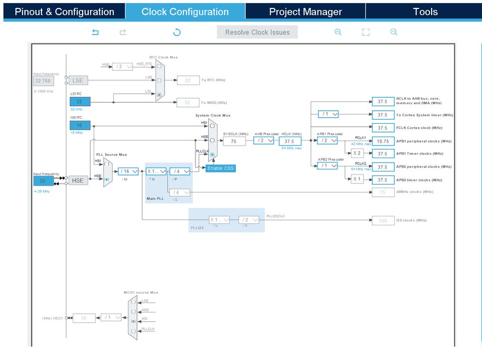
Step 4: Configure Your Clock
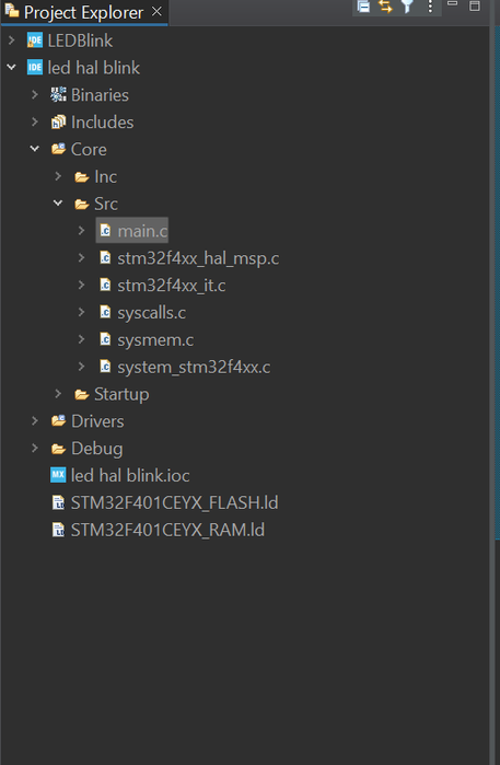
Step 5: Open Main.c File
GOTO Project and find main.c file
Step 6: Goto While(1) in Main() and Add Your Code
I use GPIO Pin 13 you may use other GPIO Pins
HAL_GPIO_WritePin(GPIOC, GPIO_PIN_13, 1);
HAL_Delay(500);
HAL_GPIO_WritePin(GPIOC, GPIO_PIN_13, 0);
HAL_Delay(500);

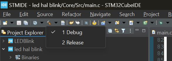
Step 7: Debug
Open and Click On Debug(1)
Step 8: Copy Path of .elf File Generated
Right click on Project and click on show in system explorer and copy the path

Step 9: Open STMCubeProgrammer and Connect to STM Board Via USB
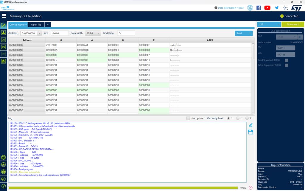
Step 10: Click on Open File and Paste the Copied Path
Step 11: Go to Download Options (Found in Toolbar on the Left)

Step 12: Change Download Options and Click on "Start Automatic Mode"

Step 13: The Final Step

The LED starts blinking


![Tim's Mechanical Spider Leg [LU9685-20CU]](https://content.instructables.com/FFB/5R4I/LVKZ6G6R/FFB5R4ILVKZ6G6R.png?auto=webp&crop=1.2%3A1&frame=1&width=306)


