Introduction: Matrix Display Clock With Arduino Nano
Time Matrix The clock with Arduino Nano
An exciting journey through the creation of my own personalized digital watch! You'll see every step in detail, from CAD design to 3D printing, assembly and breadboard testing. You will discover how I transformed an idea into a working clock, with all the key steps to realize your project.
Supplies
MAX7219 8x32 4 in 1 Dot Matrix LED Display Display Module Compatible with Arduino
Arduino Nano Nano-V3.0 ATMEGA-328
Threaded Inserts M2 M2,5 M3, M4 and M5
Prototyping perfboards
Miniature panel mount push buttons
Thin electrical wires
Step 1: Programming the Arduino Nano Module
/*
  Channel Name: Romano Giuseppe - Electronic & CNC LAB
  Channel Link: https://www.youtube.com/@Electronic.CNCLab
  Project Description: This Arduino UNO project utilizes a MAX7219 LED Matrix and an RTC (Real-Time Clock) module
  to display the current time. The U8g2 library is used for controlling the LED Matrix, and the RTClib library
  is used for interfacing with the RTC module. The time is updated every second and displayed in HH:MM format.
*/


#include <Arduino.h>
#include <U8g2lib.h>
#include "RTClib.h"


// Constants for pins and time durations
const int RTC_POWER_PIN = 4;
const int DISPLAY_CONTRAST = 40;
const int UPDATE_INTERVAL = 500;  // 0.5 second


// Constants for button pins
const int HOUR_BUTTON_PIN = 8;
const int MINUTE_BUTTON_PIN = 9;
const int ZERO_SEC_PIN = 7;


// Variable to keep track of the button state (zero second)
bool zeroButtonState = false;


// Initialize RTC and U8g2 objects
RTC_DS1307 rtc;


// Initialize the U8g2 object for controlling the MAX7219 LED Matrix
// Parameters: rotation, clock pin, data pin, chip select pin, data/command pin, reset pin
U8G2_MAX7219_32X8_F_4W_SW_SPI u8g2(
  U8G2_R0,        // Rotation: No rotation
  11,             // Clock pin: 11
  12,             // Data pin: 12
  10,             // Chip Select (CS) pin: 10
  U8X8_PIN_NONE,  // Data/Command (DC) pin: None
  U8X8_PIN_NONE   // Reset pin: None
);


// Global variable to hold the time string
char time_string[10];


// Function Prototypes
void initializeRTC();
void updateTimeString();
void checkButtons();


// Variable to keep track of the colon's state
bool showColon = true;  //


void setup() {
  // Initialize RTC
  initializeRTC();


  // Initialize U8g2 library
  u8g2.begin();
  u8g2.setContrast(DISPLAY_CONTRAST);


  // Initialize button pins
  pinMode(HOUR_BUTTON_PIN, INPUT_PULLUP);
  pinMode(MINUTE_BUTTON_PIN, INPUT_PULLUP);
  pinMode(ZERO_SEC_PIN, INPUT_PULLUP);  //
}


void loop() {


  zeroButtonState = digitalRead(ZERO_SEC_PIN);
  if (zeroButtonState == LOW) {
    DateTime now = rtc.now();
    rtc.adjust(DateTime(now.year(), now.month(), now.day(), now.hour(), now.minute(), 0));
  }


  // Update the time string
  updateTimeString();


  // Set the font and clear the buffer
  u8g2.setFont(u8g2_font_t0_11b_tr);
  u8g2.clearBuffer();


  if (showColon) {
    u8g2.drawStr(2, 8, time_string);
  } else {
    char tempString[10];
    snprintf(tempString, sizeof(tempString), "%02d %02d", rtc.now().hour(), rtc.now().minute());
    u8g2.drawStr(2, 8, tempString);
  }


  // Draw the time string and send it to the display


  u8g2.sendBuffer();
  showColon = !showColon;


  // Wait for the update interval
  delay(UPDATE_INTERVAL);


  // Check for button presses to adjust time
  checkButtons();
}


void initializeRTC() {
  // Power the RTC module
  pinMode(RTC_POWER_PIN, OUTPUT);
  digitalWrite(RTC_POWER_PIN, HIGH);


  // Initialize the RTC module
  if (!rtc.begin()) {
    Serial.begin(9600);
    Serial.println("RTC initialization failed!");
    abort();
  }
}


void updateTimeString() {
  // Get the current time
  DateTime now = rtc.now();


  // Format the current time into the time_string variable
  // Parameters: destination buffer, format string, current hour, current minute
  sprintf(
    time_string,  // Destination buffer: Array where the formatted string will be stored
    "%02d:%02d",  // Format string: Specifies the format (Hour:Minute)
    now.hour(),   // Current hour: Obtained from the RTC module
    now.minute()  // Current minute: Obtained from the RTC module
  );
}


void checkButtons() {
  // Check if the hour button is pressed
  if (digitalRead(HOUR_BUTTON_PIN) == LOW) {
    DateTime now = rtc.now();
    rtc.adjust(DateTime(now.year(), now.month(), now.day(), (now.hour() + 1) % 24, now.minute(), now.second()));
    delay(200);  // Debounce delay
  }


  // Check if the minute button is pressed
  if (digitalRead(MINUTE_BUTTON_PIN) == LOW) {
    DateTime now = rtc.now();
    rtc.adjust(DateTime(now.year(), now.month(), now.day(), now.hour(), (now.minute() + 1) % 60, now.second()));
    delay(100);  // Debounce delay
  }
}
Step 2: 3D Printed Parts
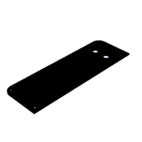
Cad files in STL format, necessary to create the clock with matrix display with Arduino Nano
Step 3: Practical Implementation
Step 4: Wiring Diagram and Practical Diagram
Practical connection diagram


![Tim's Mechanical Spider Leg [LU9685-20CU]](https://content.instructables.com/FFB/5R4I/LVKZ6G6R/FFB5R4ILVKZ6G6R.png?auto=webp&crop=1.2%3A1&frame=1&width=306)


