

Introduction: Mini Self-balancing Robot


Greetings,
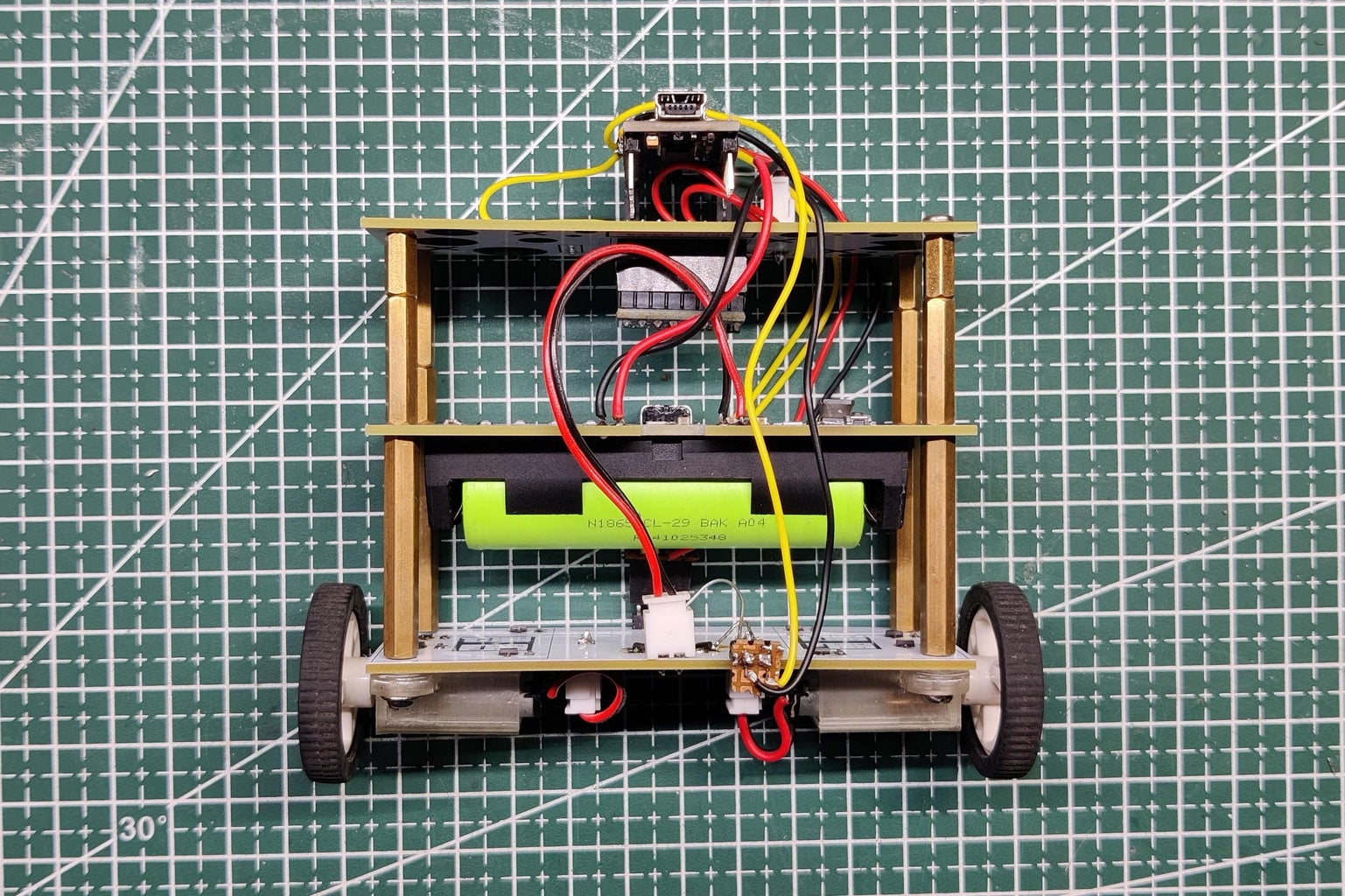
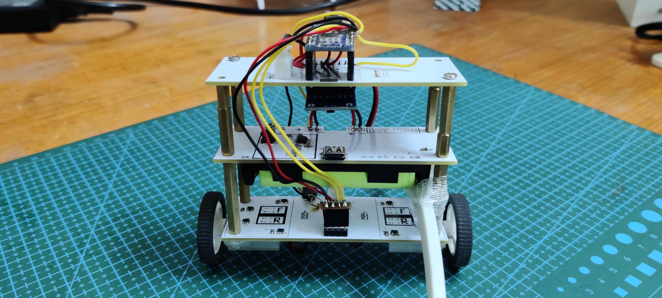
So here's an interesting little project: a Mini Self-Balancing Bot made from three layers of custom PCB, each containing a specialized circuit for this robot's operation.
The ground layer includes a motor driver constructed by combining N-channel Mosfets to form an H-bridge motor driver for controlling two DC motors.
The second layer is made up of a lithium cell and its charging and boost IC, which raises the 3.7V of the lithium-ion cell to a stable 5V so that electronics can function.
The third and topmost layer is the microcontroller layer, which is made up of a Seeed XIAO ESP32 C3 MCU connected to an MPU6050 Module; later in this project, the XIAO was replaced with an Arduino Nano.
The MPU6050 is used as the main gyro accelerometer sensor in this project, which handles real-time reading of the robot's position and orientation, which is then read by the XIAO DEV Board, which causes the motor to move forward and backward to balance the robot.
I've made a similar robot in the past; it was massive and featured a large 12V DC motor. This version employs a smaller 3V gear DC motor that is powered by a 3.7V 2200mAh lithium cell linked to an IP5306 Boost Module configuration.
This project is still in its early stages. The code must be edited, and the motor driver must be tweaked slightly.
For the time being, this project works, but the self-balancing portion has not been completed. This article covers all of the steps involved in the construction of this project, as well as what will happen next and what changes are required.
Let's get started.
Supplies
These are the materials used in this built-
- Custom PCBs
- Seeed XIAO ESP32 C3
- AO3400 N channel Mosfet SOT23 Package
- Custom PCB
- 10K resistors 0603 Package
- 2R 1206 package
- JST connectors
- Vertical Header pin male connector
- Micro gear motor
- 3D printed Motor Holder
- MPU6050
- Lithium Cell
- IP5306
- 1uF 0805 Capacitors
- SMD Switch
- 1uH SMD Inductor
- Arduino Nano
Step 1: Design
This design did not necessitate any major 3D Printed components, so no 3D Model was required; however, we reused 3D Printed Micro Gear Motor Holders from a previous project, which was this-
https://www.instructables.com/Dual-Motor-Driver-As-Robot-Base/
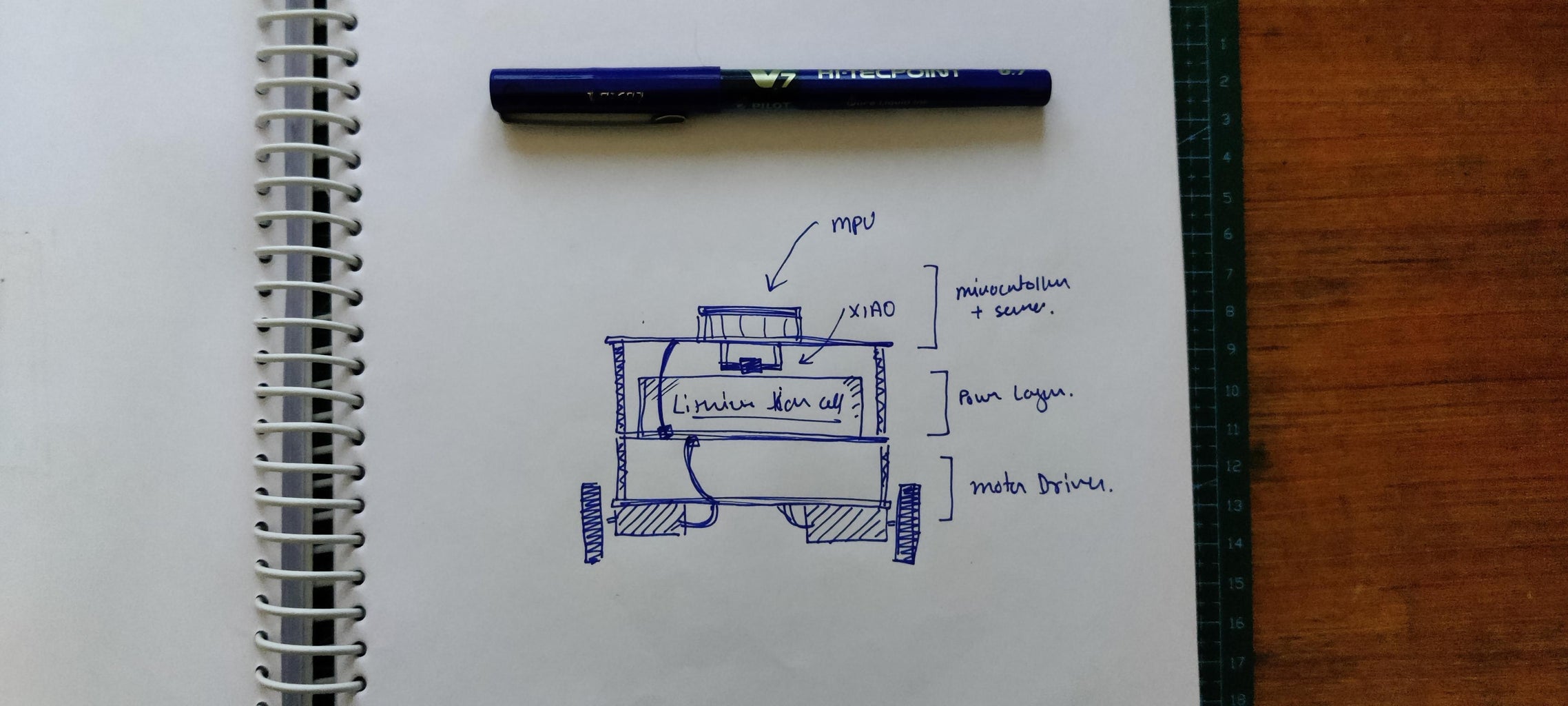
The idea was simple: we have three boards with the same dimensions (95mm x 35mm) and mounting holes (four 2.8mm diameter holes at each vertex), so they can be easily connected using PCB standoffs.
We used a 3D-printed motor mount with two holes on each side to mount the motor on the base PCB.
The middle layer will house the battery, while the top layer will house the gyro sensor and microcontroller.

Step 2: PCB Design


This project's PCB design consists of three boards, which are as follows.
- Motor Driver Board
- Battery Board
- Microcontroller and Gyro Board
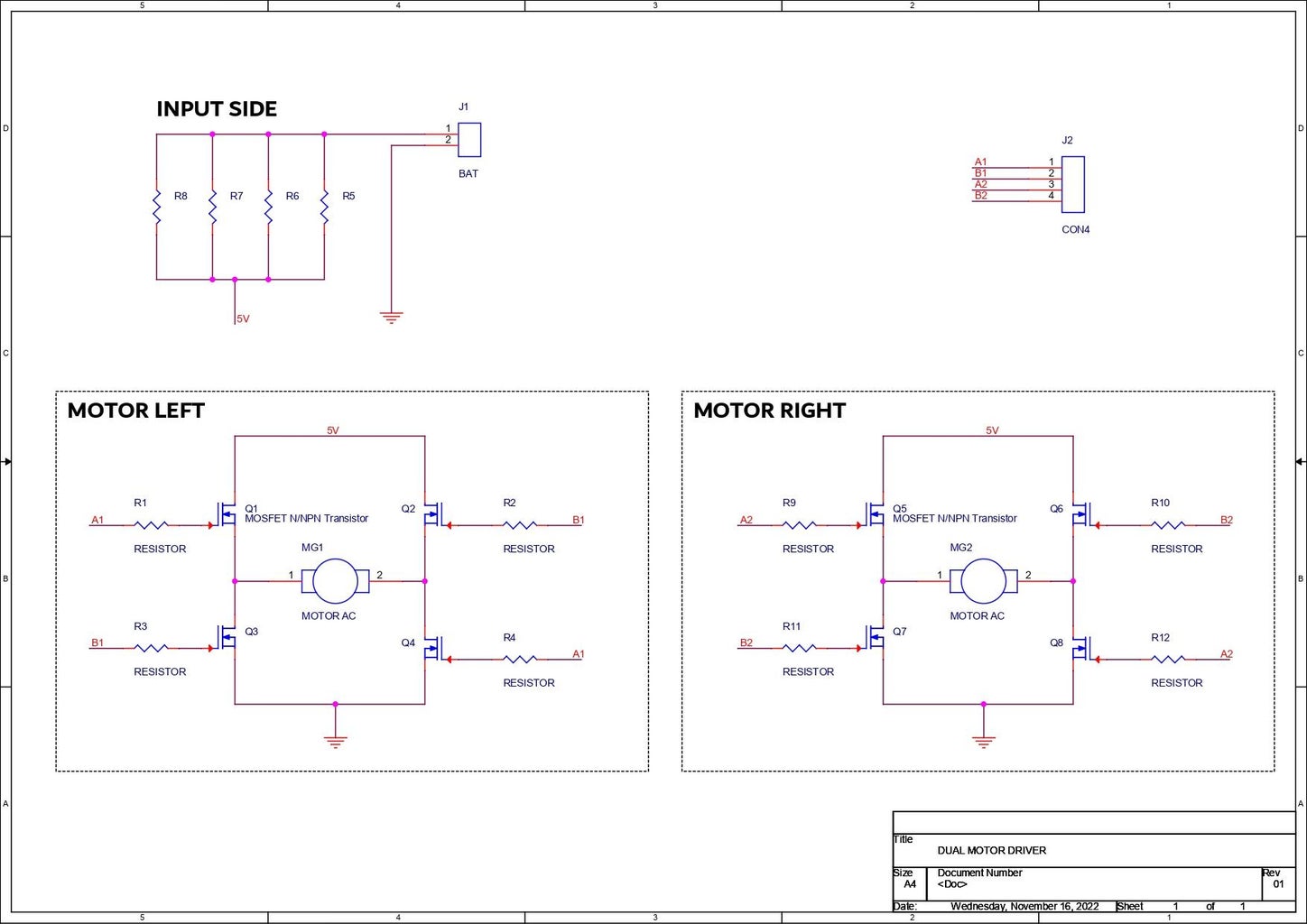
The motor driver board is made up of eight N channel AO3400 mosfets that are all connected in a H bridge configuration to control two motors. Each H bridge is made up of four N channel mosfets.
The H-bridge is a unique circuit that can change the polarity of the voltage applied to any load; it is commonly used with motors to change their rotation from backward to forward and can be made of switches.
The first two FETs (Q1 and Q2) are connected in such a way that their drains are connected to the VCC or Power source that will drive the motor.
The sources of Q1 and Q2 are both connected to the positive and negative sides of the motor.
Two more FETs Q3 and Q4 Drain are linked to Q1 and Q2 sources, as well as the motor terminals.
The Q3 and Q4 Sources are linked to GND.
The gates of Q1 and Q4 are connected together, and the gates of Q2 and Q3 are connected together. If we apply a signal to Q1, Q4 will also get activated, and if the signal is applied to Q2, Q3 will get activated.
1 and 0 will be denoted for HIGH and LOW, respectively. We set Gate of Q1 to 1 and Gate of Q2 to 0, and this turns the motor in one direction. If we set Gate of Q1 to 0 and Gate of Q2 to 1, the polarity of the motor changes, and it starts rotating in the opposite direction.
If both Q1 and Q2 are 1, then a short circuit will occur.
There are a total of two H-bridges on the Base Board which is for controlling both motors.
Additionally, I have added four Load Resistors between the Battery Positive and the input of the H-Bridge. this will limit the current going into the motors.
There's also a CON4 header pin that separates the gates of both H-bridges so we can connect them to a microcontroller to drive the motors.
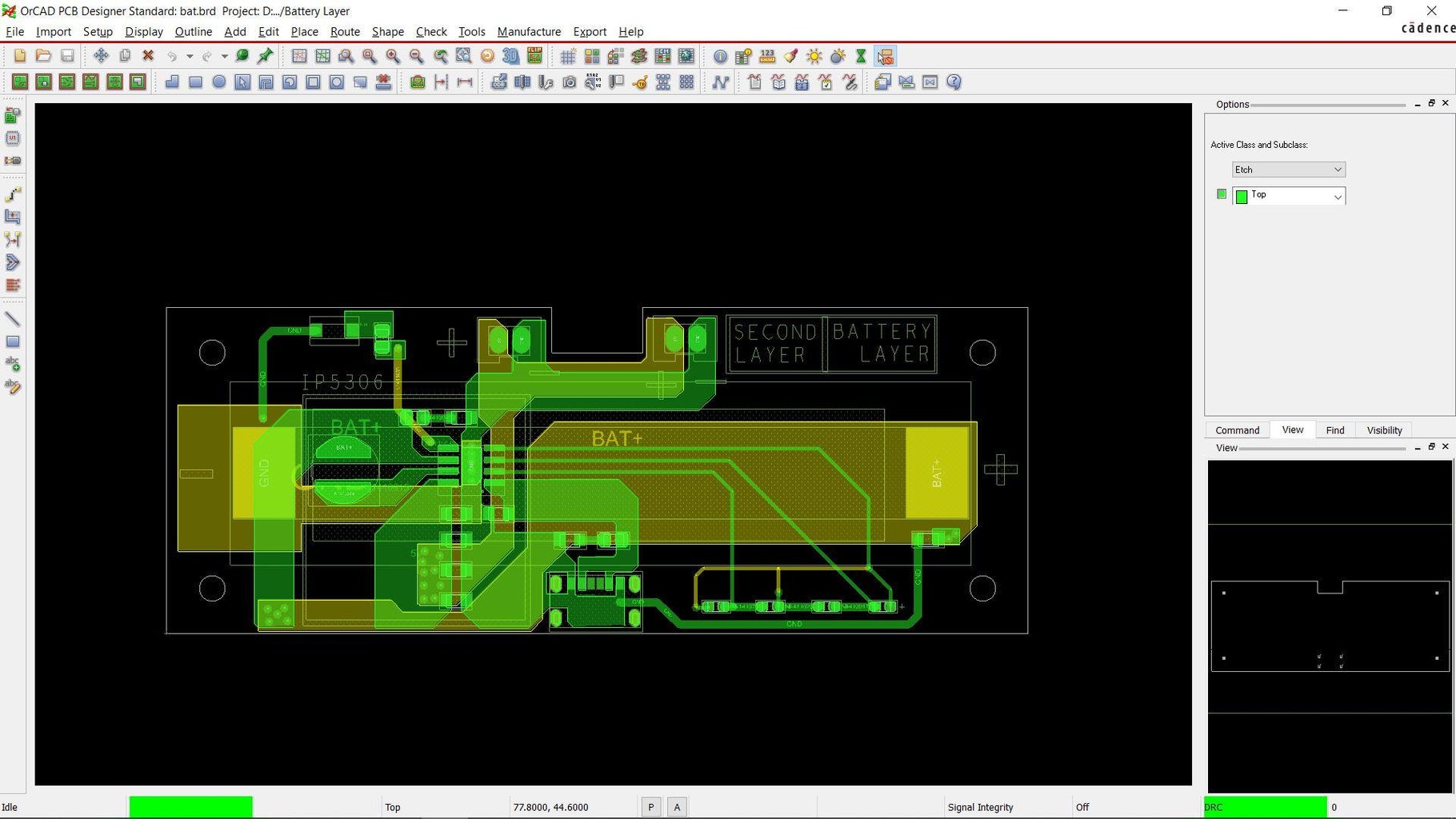
The Battery Board is a simple IP5306 IC-based setup that is a power management setup for Lithium Ion cells; it boosts the lithium cell's 3.7V into constant 5V and has a battery indication feature, LED indication for battery charge level, and low and high voltage cuts, making this setup perfect for a small robot project that requires 5V input with a single lithium cell.
you can read more about IP5306 from its datasheet -
http://www.injoinic.com/wwwroot/uploads/files/20200221/0405f23c247a34d3990ae100c8b20a27.pdf
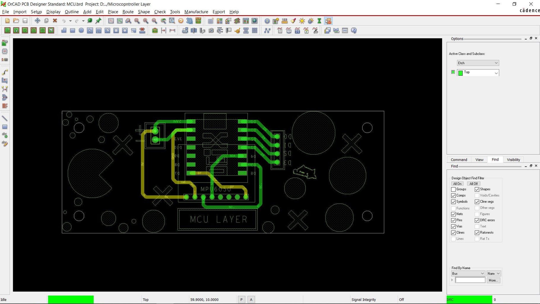
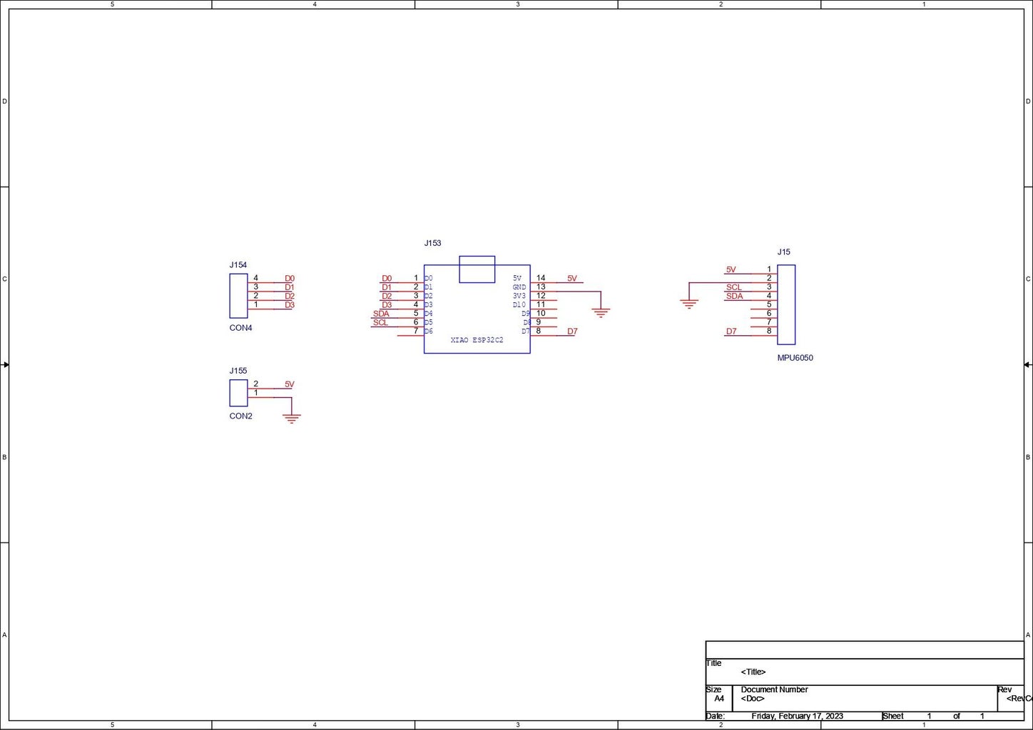
Finally, we use a microcontroller and the GRYO board, which is a simple breakout board for the XIAO ESP32 Board, which is connected to the MPU6050 sensor module and has a CON2 port for power input and a CON4 port for Motor Driver control pin output.
All three boards were modeled using same board outline, only the component placement was changed.
Step 3: Seeed Studio Fusion Service


As for the PCBs in this project, they were sent to SEEED Studio for samples.
An order was placed for a white solder mask with black silkscreen for all boards.
PCBs arrived in less than a week, which was super fast.
The quality was very good considering the price, which was also pretty low.
The PCB quality of bothPCBs was just awesome!
Seeed Fusion PCB Service offers one-stop prototyping for PCB manufacture and PCB assembly, and as a result, they produce superior quality PCBs and Fast Turnkey PCBA within 7 working days.
Seeed Studio Fusion PCB Assembly Service takes care of the entire fabrication process, from PCB manufacturing and parts sourcing to assembly and testing services, so you can be sure they are getting a quality product.
After gauging market interest and verifying a working prototype, Seeed Propagate Service can help you bring the product to market with professional guidance and a strong network of connections.
Next, we prepare for the PCB assembly process.
Step 4: XIAO MCU Board Assembly


- The TOP Layer is the microcontroller and gyro board, which consists of an XIAO Board with MPU6050.
- We solder two CON7 header pins on XIAO pads and one CON8 in place of MPU6050, and that's pretty much the end of the assembly process for this board.
- Then, on one side, we insert XIAO, and on the other, we insert MPU.
Step 5: Test Sketch for MPU6050

The MPU6050 is a well-known sensor module that integrates a three-axis gyroscope and a three-axis accelerometer into a single package. It also has an on-board Digital Motion Processor (DMP) that allows complex calculations to be offloaded from the main microcontroller, greatly simplifying the implementation of motion tracking in embedded systems.
Here are some key features of the MPU6050:
- Six degrees of freedom (6DoF) sensing: The MPU6050 can detect motion along the X, Y, and Z axes using both the accelerometer and the gyroscope.
- Digital Motion Processor: The on-board DMP can perform complex calculations such as motion fusion and sensor calibration, offloading this processing from the main microcontroller.
- Wide operating voltage range: The MPU6050 can operate on a voltage range of 2.3V to 3.4V.
- Communication interface: The module can communicate with a microcontroller using either I2C or SPI.
- Low power consumption: The MPU6050 consumes only 3.9mA in full operating mode, making it suitable for use in low-power applications.
The MPU6050 is commonly used in applications such as quadcopters, robotics, gaming, and wearable devices.
We need to install the MPU6050 library before uploading the below test sketch.
https://github.com/adafruit/Adafruit_MPU6050
- We open example sketches> Adafruit MPU6050> plotter and upload it into the XIAO Board.
- Next, we go to Tool Menu>Serial Plotter which will open the graphs which will be plotted by using readings taken by MPU6050.
Readings will change if we move the microcontroller board up, down, left, or right.
This sketch will show that the MPU is working with the XIAO setup.
Step 6: Battery Board Assembly


- We begin with the solder paste dispensing process, applying solder paste to each component pad individually.
- We then used an ESD tweezer to carefully pick and place all the SM components in their assigned places one by one.
- After the "pick and place process, " we carefully lifted the whole circuit board and placed it on the Reflow hotplate.
- We then put the Lithium cell holder on bottom side of the board using soldering iron.
- Board assemby is now completed.
Step 7: Battery Board Test


- Before we use this Bboardoard in Robot, we need to make sure it works.
- We place a lithium cell in its holder on the bottom and use a multimeter to measure its output voltage, which should be 5 volts.
- Finally, we connect a smartphone charger's Type-C port to this board to see if it charges.
- The indicator leds were blinking, indicating that the cell was charging; this concludes testing, and we can now proceed to the main assembly process.
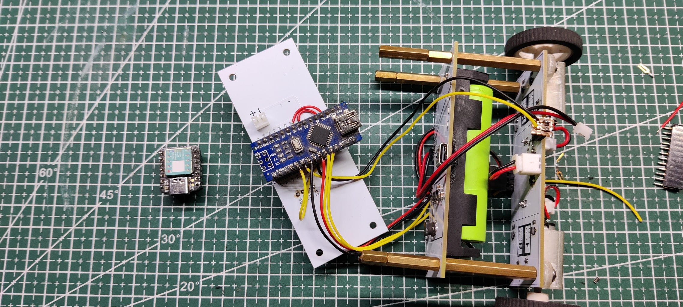
Step 8: Robot Assembly


- We begin the main assembly by connecting all three boards together, with the battery board's 5V and GND connected to the microcontroller board and motor driver board. The XiAO CON4 Port is linked to the motor driver input to control the gate of fets.
- We temporarily remove the wiring from the motor driver board in order to add motor mounts and PCB standoffs to the board.
- Next, we use PCB standoffs to connect the battery board to the motor driver board, and we add four more standoffs to the battery layer to connect the top layer.
- After connecting all of the wires that were previously added, the assembly is complete.
Step 9: Main Sketch
Here's the main sketch that is being used in this built-
#include <PID_v1.h>
#include <LMotorController.h>
#include "I2Cdev.h"
#include "MPU6050_6Axis_MotionApps20.h"

#if I2CDEV_IMPLEMENTATION == I2CDEV_ARDUINO_WIRE
 #include "Wire.h"

#endif

#define MIN_ABS_SPEED 10

MPU6050 mpu;

// MPU control/status vars
bool dmpReady = false; // set true if DMP init was successful
uint8_t mpuIntStatus; // holds actual interrupt status byte from MPU
uint8_t devStatus; // return status after each device operation (0 = success, !0 = error)
uint16_t packetSize; // expected DMP packet size (default is 42 bytes)
uint16_t fifoCount; // count of all bytes currently in FIFO
uint8_t fifoBuffer[64]; // FIFO storage buffer

// orientation/motion vars
Quaternion q; // [w, x, y, z] quaternion container
VectorFloat gravity; // [x, y, z] gravity vector
float ypr[3]; // [yaw, pitch, roll] yaw/pitch/roll container and gravity vector

//PID
double originalSetpoint = 173;
double setpoint = originalSetpoint;
double movingAngleOffset = 0.1;
double input, output;

//adjust these values to fit your own design
double Kp = 150;   //too little KP will make robot fall
double Kd = 20; //to decrease the oscillation
double Ki = 270;
PID pid(&input, &output, &setpoint, Kp, Ki, Kd, DIRECT);

double motorSpeedFactorLeft = 0.5;
double motorSpeedFactorRight = 0.5;

//MOTOR CONTROLLER
int ENA = 3;
int IN1 = 4;
int IN2 = 6;
int IN3 = 7;
int IN4 = 8;
int ENB = 5;
LMotorController motorController(ENA, IN1, IN2, ENB, IN3, IN4, motorSpeedFactorLeft, motorSpeedFactorRight);

volatile bool mpuInterrupt = false; // indicates whether MPU interrupt pin has gone high
void dmpDataReady()
{
 mpuInterrupt = true;
}


void setup()
{
 // join I2C bus (I2Cdev library doesn't do this automatically)
 #if I2CDEV_IMPLEMENTATION == I2CDEV_ARDUINO_WIRE
 Wire.begin();
TWBR = 24; // 400kHz I2C clock (200kHz if CPU is 8MHz)
 #elif I2CDEV_IMPLEMENTATION == I2CDEV_BUILTIN_FASTWIRE
 Fastwire::setup(200, true);
 #endif

 mpu.initialize();

 devStatus = mpu.dmpInitialize();

 // supply your own gyro offsets here, scaled for min sensitivity
 mpu.setXGyroOffset(220);
 mpu.setYGyroOffset(76);
 mpu.setZGyroOffset(-85);
 mpu.setZAccelOffset(1788); // 1688 factory default for my test chip

 // make sure it worked (returns 0 if so)
 if (devStatus == 0)
 {
 // turn on the DMP, now that it's ready
 mpu.setDMPEnabled(true);

 // enable Arduino interrupt detection
 attachInterrupt(0, dmpDataReady, RISING);
 mpuIntStatus = mpu.getIntStatus();

 // set our DMP Ready flag so the main loop() function knows it's okay to use it
 dmpReady = true;

 // get expected DMP packet size for later comparison
 packetSize = mpu.dmpGetFIFOPacketSize();

 //setup PID
 pid.SetMode(AUTOMATIC);
 pid.SetSampleTime(10);
 pid.SetOutputLimits(-255, 255);
 }
 else
 {
 // ERROR!
 // 1 = initial memory load failed
 // 2 = DMP configuration updates failed
 // (if it's going to break, usually the code will be 1)
 Serial.print(F("DMP Initialization failed (code "));
 Serial.print(devStatus);
 Serial.println(F(")"));
 }
}


void loop()
{
 // if programming failed, don't try to do anything
 if (!dmpReady) return;

 // wait for MPU interrupt or extra packet(s) available
 while (!mpuInterrupt && fifoCount < packetSize)
 {
 //no mpu data - performing PID calculations and output to motors
 pid.Compute();
 motorController.move(output, MIN_ABS_SPEED);

 }

 // reset interrupt flag and get INT_STATUS byte
 mpuInterrupt = false;
 mpuIntStatus = mpu.getIntStatus();

 // get current FIFO count
 fifoCount = mpu.getFIFOCount();

 // check for overflow (this should never happen unless our code is too inefficient)
 if ((mpuIntStatus & 0x10) || fifoCount == 1024)
 {
 // reset so we can continue cleanly
 mpu.resetFIFO();
 Serial.println(F("FIFO overflow!"));

 // otherwise, check for DMP data ready interrupt (this should happen frequently)
 }
 else if (mpuIntStatus & 0x02)
 {
 // wait for correct available data length, should be a VERY short wait
 while (fifoCount < packetSize) fifoCount = mpu.getFIFOCount();

 // read a packet from FIFO
 mpu.getFIFOBytes(fifoBuffer, packetSize);

 // track FIFO count here in case there is > 1 packet available
 // (this lets us immediately read more without waiting for an interrupt)
 fifoCount -= packetSize;

 mpu.dmpGetQuaternion(&q, fifoBuffer);
 mpu.dmpGetGravity(&gravity, &q);
 mpu.dmpGetYawPitchRoll(ypr, &q, &gravity);
 input = ypr[1] * 180/M_PI + 180;
 }
}
Before using this code, you need to download the following libraries-
- MPU6050 library- https://github.com/adafruit/Adafruit_MPU6050
- L motor controller library- https://github.com/lukagabric/Franko/blob/master/l...
- PID Library- https://github.com/br3ttb/Arduino-PID-Library/blob...
We began by installing the MPU6050 library and uploading one of its example sketches, a plotter sketch.
The graph changes as the robot moves up and down, indicating that the MPU6050 is functioning properly.
Now upload the main code but before uploading, remember to change Motor pinouts according to your connection.
also, after uploading the sketch, your robot might not balance itself properly, so we have to tweak few values which are these
- To increase the stability of the robot, KP will make the robot fall
- KD will increase the oscillation!
by editing these values, your robot will become more stable, but by putting the wrong values, your robot might become more unstable.
Step 10: Error in Board
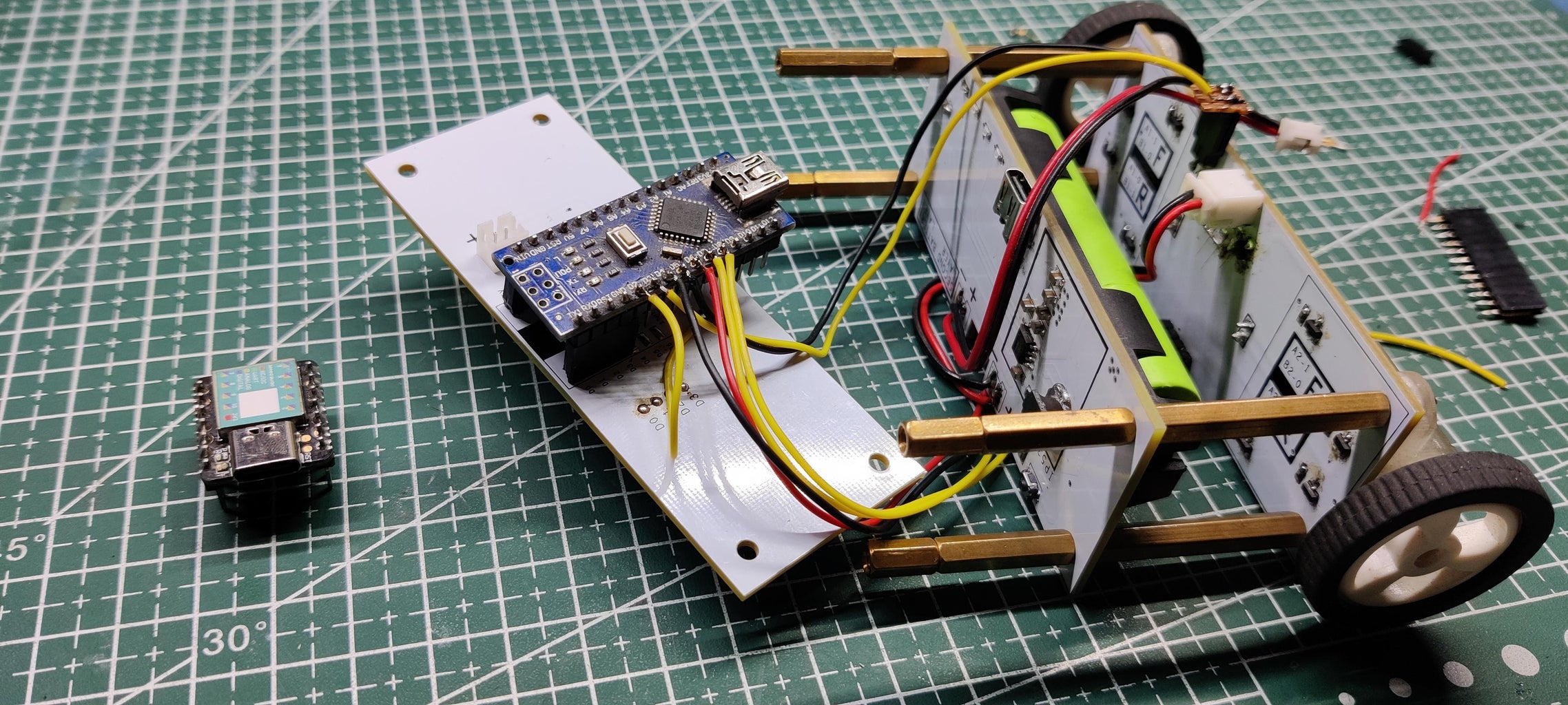
Because XIAO had some issues with the main code, I had to remove it from the board and replace it with the Arduino Nano. As a result of this change, I had to rewire everything, which meant that the pinout had to be reduced and manually soldered to the Arduino Nano's pins.
The main code worked with nano, but there was a problem with the motor driver, which caused mosfets to fail frequently.
Step 11: Conclusion


The gyro part worked, but it had sensitivity issues, so a support was added to keep the robot from falling over. The motor driver had noise issues, and the motor randomly turned on and off without providing its gate signal.
Overall, this project was a shambles, but here's what needed to be changed in Version 2: the motor driver board requires diodes and two additional fets to enable each section's power flow, and much more powerful fets should be installed instead of the AO3400 SOT23-3 package.
The microcontroller layer must then be modified in accordance with the Arduino nano setup.
We will be able to run this small bot by making these changes; it currently works but not perfectly.
Special thanks to Seeed Studio for providing PCBs for this project, do check them out if you need great PCB Service for less cost.
Stay tuned for the next version; all project documentation is attached; if you need assistance with this project, please DM me or leave a comment.
Peace out and I'll be back with a V2 soon!

Participated in the
Big and Small Contest


![Tim's Mechanical Spider Leg [LU9685-20CU]](https://content.instructables.com/FFB/5R4I/LVKZ6G6R/FFB5R4ILVKZ6G6R.png?auto=webp&crop=1.2%3A1&frame=1&width=306)


